
Nomenclature
Af Surface area of fin
At Surface area of the tube without fins
cp Specific heat
C1ԑ, C2ԑ, Cμ Turbulence model constants
Dc Fin collar outside diameter
Df Fin diameter
Dp Perforation diameter
Dt Tube diameter
f Friction factor
GPC Global performance criterion
h Heat transfer coefficient
hf Fin height
hs Segment height of the serrated fin
k Turbulent kinetic energy
ka Thermal conductivity of air
kalThermal conductivity of aluminum
$\dot{m}$ Mass flow rate of air
Mf Fin mass
${{M}_{{{G}_{PC}}}}$ Mass global performance criterion
Nu Nusselt number
PEC Performance evaluation criterion
Pl Longitudinal tube pitch
Pr Prandtl number
Pt Transverse tube pitch
ΔP Pressure drop
Q Heat transfer rate
Re Reynolds number based on fin collar outside diameter
S Fin spacing
St Tube shift
tf Fin thickness
T Temperature
Ta Average air temperature
Tf Fin temperature
Tin Air inlet temperature
Tout Air outlet temperature
Tt Tube surface temperature
$\Delta {{T}_{LMTD}}$ Logarithmic mean temperature difference
u Velocity
uin Inlet velocity
umax Maximum air velocity at minimum cross-section
$\dot{V}$ Volumetric flow rate of air
ws Serrated fin segment width
Greek symbols
αp Inverse Prandtl number
ԑ Turbulent energydissipationrate
η Fin efficiency
μa Dynamic viscosity of air
ρa Density of air
1. Introduction
The finned-tube heat exchangers are widely applied in heat generation systems such as the cooling of ships and submarine engines, stations of oil exploitation in deeper seas, submerged towers of offshore hybrid wind turbines, and hydrocarbon pumping stations in seas and oceans. Also, understanding the phenomenon of vortex shedding and the recirculation zone between and behind the tubes is a cardinal problem in ocean and marine engineering structures [1], [2], [3], [4]. Undoubtedly the main purpose of the fins is to strengthen the flow mixture, reduce the recirculating region, and dissipate the heat generated to its surroundings to keep the best thermal working conditions of the system. The annular finned tube is widely encountered in various applications due to its low manufacturing cost and significant efficiency [5,6]. Furthermore, this fin geometry needs enhancement in heat transfer and pumping power with increasingly small volumes, weights, and costs. Various fin designs have been developed to improve the efficiency of heat exchangers (HEs), such as the eccentric circular fins, perforated fins, serrated fins, star-shaped fins, and concentric circular fins.
For concentric circular finned-tube (CCFT), several authors examined the impact of fin dimensions on the overall characteristics of heat exchangers. Mon and Gross [7] numerically investigated the turbulent hydrothermal factors in a bundle of four rows with concentric circular finned tubes (CCFT). Performing this same numerical simulation in the case of a single row with CCFT, Bilirgen et al. [8] inspected the influence of fin height, fin spacing, fin thickens, fin material, and Reynolds number on the convective thermal exchange and pressure losses. For a finned-tube bundle, Benmachiche et al. [9] employed the thermography technique to determine the thermal exchange coefficients over circular plane fins for both staggered and aligned configurations.
Recently, the thermodynamic efficiency of air-cooled HE was computationally examined by Unger et al. [10]. They inspected the impact of the number of tube rows, tube shape, and its configuration, as well as the transversal and longitudinal tube pitch on the thermal behavior. The best thermal exchange was provided with the staggered layout. Also, the oval tube shape (with 1:2.1 in the aspect ratio) and circular tube shape were optimum for the staggered and inline arrangements, respectively. Five rows of tubes were also found to be the optimum number for the maximum thermal performances.
Several researchers reported that the eccentric circular finned-tube (ECFT) and the perforated circular finned-tube (PCFT) enhance the flow mixing, decrease the size of the air-side recirculation behind the tubes, and increase the thermal efficiency. For HEs with a single row of tubes, Tahrour et al. [11] numerically compared the hydrothermal behaviors of concentric and eccentric CFTs. By experiments and CFD simulations, Benmachiche et al. [12] inspected the thermal-hydraulic characteristics of ECFT and CCFT having four rows of tube bundles. Their results showed that for both staggered and aligned arrays, the thermal features of the ECFT are greater than that of the CCFT. A decrease in pressure losses accompanied this improvement in the thermal exchange. Senapati et al. [13] numerically inspected the impact of eccentricity on the convection over a finned cylinder under different fin spacing and diameter values and tube base temperature. For aluminum fins with a fixed fin diameter, the researchers noticed decreased thermal exchange rates with an increasing fin eccentricity.
Similarly, Fourar et al. [14] numerically inspected the impact of eccentricity on the thermal exchange as a function of the diameter, thicknesses, material, and spacing of the fin for Re ranging between 4 × 10⁴ and 7 × 10⁷. The results demonstrated that the eccentricity impact is significant in fins with a small diameter and high conductivity materials. In addition, the fins with great thickness yield the highest thermal exchange rate regardless of their eccentricity.
For CFTs, the effect of holes insertion and their angular location on the thermal transfer has been experimentally inspected by Yakar and Karabacak [15]. For Re higher than the critical value, they noticed that the Nusselt number (Nu) is higher by about 12% for the perforated circular finned-tube (PCFT) than the plain CFT. Lee et al. [16] and Banerjee et al. [17] noticed that the surfaces with perforations enhance the hydrothermal characteristics of HEs. In Ref. [16] and for PCFT, the researchers experimentally evaluated the hydrothermal behavior for 2-hole and 4-hole configurations. The fin factor, which is determined as the ratio between the thermal exchange coefficient and the pressure drop, was equal to 5.19 and 1.59 for the 2-and 4-hole PCFT, respectively.
Using the commercial software ANSYS FLUENT, Lee et al. [18] numerically inspected the impact of the position of perforations (90°,120°, and 150°) on the overall characteristics of spiral finned-tube HEs. They reported that the area goodness coefficient, which considers the relationship between the thermal exchange and the pressure losses, is the most significant for the perforated fins. Recently, Maleki et al. [19] analyzed the impacts of perforation geometry (shape and size) on heat transfer and flow physics for the case of perforations plate-fin heat sinks. The numerical results showed that for a constant perforations size, change in perforations shape enhanced the heat transfer performance, perforated fin efficiency, and fin optimization factor by more than 40%, 45%, and 110%, respectively.
Abundant literature regarding the serrated circular finned-tube (SCFT) and star-shaped finned-tube (S-SFT) has been published. The interruption of fins enhances the re-attachment of the boundary layer near the thermal exchange walls and improves the flow mixing. This motivated the researchers to focus on the efficiency of SCFT and S-SFT thermal devices. For various values of height and pitch of fins, Reynolds number, and tube bundle layout, Naess [20] experimentally analyzed the efficiency of finned-tube bundles. The thermal exchange reached its maximum value when the flow areas became equal in the diagonal and transverse directions.
The increased fin height yielded an enhancement in the thermal exchange coefficient, whereas the augmented fin pitch yielded a reduction in the rates of the thermal exchange and pressure losses. They also observed a negligible impact of the fin height on the pressure losses. Lemouedda et al. [21] inspected the influence of fin twisting and the number of fin segments on the efficiency of spiral finned tubes with serrated and non-serrated fins. For the same thermal exchanger area, the best performances were observed with the serrated fin tubes (SFTs). In addition, the increasing number of fin segments improved the SFTs efficiency.
For one tube with serrated fins, Anoop et al. [22] inspected the influence of the thickness, pitch, and height of fins, serration depth, and the flow attack angle on the overall performances. Lindqvist and Næss [23] performed numerical simulations for eight rows of staggered banks of serrated fins to evaluate hydrothermal details. The evaluation of the exchanger performance was done by empirical correlations for Nusselt and Euler numbers. Zhou et al. [24] were interested in studying the hydrothermal characteristics of the air-side for ten rows staggered bank of serrated spiral fin-and-tube HEs. The influence of varied water vapor content and twisted angle on the global performances were explored for a range of Re between 6 × 10³ and 12×103. The twisted serrated fin provided an increase in Euler number and the thermal exchange coefficient by 13% and 1.3 times, respectively, over that of the serrated fin. For the star-shaped finned-tube (S-SFT), only Bošnjaković et al. [25,26] performed experimental and numerical studies to compare its thermal-flow performance with a concentric circular finned-tube (CCFT) for a range of Re between 2000 and 13,000. It was found that the usage of S-SFT instead of CCFT led to improving the thermal exchange up to 30% for the considered turbulent Reynolds number with the decrease in the heat exchanger mass by 23.8%.
On the other hand, researchers have achieved numerous studies to compare the hydrothermal characteristics between several shapes of annular fins. Nagarani et al. [27] highlighted the utilization of the fin shape with tube bundles in cooling systems during the last two decades. Different finned-tube designs have been compared, such as circular finned-tube, elliptical finned-tube, square and cylindrical pin fins. The highest amount of thermal exchange and pressure drop was reached with the oval tubes. In addition, Kumar et al. [28] presented a CFD study of annular and plate fins in an air-cooled HE. The crimped fins gave the most significant thermal exchange coefficient among the different cases explored (plain circular, serrated fin, crimped fin, plain plate, wavy fin, and fin with delta winglet pair). Morales-Fuentes et al. [29] numerically inspected the performances of HEs with square fin, circular fin, and pin fin inserted on circular tubes. The pin finned-tube geometry proved its superiority in terms of the thermal factor over the square and circular finned tubes.
In a recently published research, extensive experiments were achieved by Unger et al. [30] to analyze the thermodynamic performances of three shapes of annular fins(circular plain fins, circular integrated pin fins, and serrated integrated pin fins for various fin spacing (between 6 and 1 mm)). The most significant amount of the volumetric heat flux density (2.72 kW/m3K) was obtained with the circular integrated pin fins at the lowest fin spacing. In another paper [31], these authors noticed that the value of the optimum efficiency strongly depends on the tube tilt angle and the fin design.
One of the main applications of heat exchangers is in electronics and high-power cooling systems, which are utilized in structures designed to use ocean resources. Modern offshore renewable energy systems from tidal currents [32,33], waves [34,35], and wind [36] sources are among the most critical systems related to ocean engineering, in which the cooling of electronic components and heat absorption from energy converter systems have a considerable role in their effectiveness [37]. Also, one of the important elements in the modern ship with electric propulsion drive is the high-power electronic insulated-gate bipolar transistor (IGBT) module. The available cooling techniques for the IGBT module or chip include finned tube heat exchangers, conventional air or fan cooling, aluminum extrusions, etc. [38]. The utilization of optimal design of finned tube heat exchangers may be an interesting technique for the cooling of IGBT chip in marine applications.
As seen from the literature above, several changes in the fin design have been introduced to augment the performances of heat exchangers used in the cooling of energy systems. Among these studies, and for the case of annular finned-tubes, only three research works analyzed and compared the heat transfer and flow physics behavior of three shapes of annular fins [29], [30], [31], but only for a single row of tubes. However, most heat exchanger applications are in the form of multiple rows of finned-tube. Therefore, the thermal-hydraulic performance of three rows staggered bank equipped with the five most efficient shapes of annular fins is investigated in this paper. The main objective of this investigation is to find, of all the tested fin shapes, the most efficient geometry of annular finned-tube HEs in cooling offshore and onshore power generation systems. The geometrical parameters of each finned-tube design are based on the optimization given in the previous studies, such as eccentric circular finned-tube (ECFT) proposed by Benmachiche et al. [12], perforated circular finned-tube (PCFT) of Lee et al. [16], serrated circular finned-tube (SCFT) of Næss [20], and star-shaped finned-tube (S-SFT) proposed by Bosnjakovic [26]. These geometrical configurations of fin were numerically analyzed and compared with the conventional concentric circular finned-tube (CCFT) for a range of Re between 4300 and 15,000. In addition to the fin geometry, the impact of fin spacing was also considered. This parameter was found to be necessary for better construction of heat exchangers.
2. Model description
2.1. Physical model
Five annular finned-tube geometries for cooling systems are studied by keeping the same diameter for each fin and tube. A schematic diagram of each finned-tube design is shown in Fig. 1, namely a concentric circular finned-tube (CCFT), an eccentric circular finned-tube (ECFT), a perforated circular finned-tube (PCFT), a serrated circular finned-tube (SCFT), and a star-shaped finned-tube (S-SFT). Cold airflows between the annular fins while a hot fluid flows through the cylindrical tubes. The solid's part (including fins and tubes) is considered made of aluminum with thermal conductivity of kal = 202.4 W/m∙K. The values of all the geometric parameters are summarized in Table 1. The schematic of the computational domain with detailed dimensions and boundary conditions is illustrated in Fig. 2.
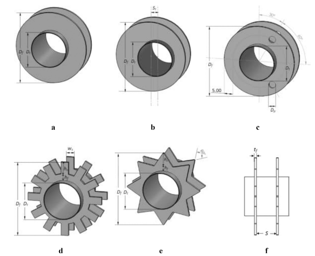
Fig. 1. Schematic of the investigated fin designs: (a) concentric circular fin; (b) eccentric circular fin; (c) perforated circular fin; (d) serrated circular fin; (e) star-shaped fin; (f) front view of the star-shaped fin. |
Table 1. Geometry of the finned-tubes (all dimensions are in mm). |
| Fin type | Tube diameterDt | Fin diameterDf | Fin spacingS | Fin thicknesstf | Transversetube pitchPt | Longitudinal tube pitchPl | Segment widthws | Segmentheighths | PerforateddiameterDp | TubeshiftSt |
|---|---|---|---|---|---|---|---|---|---|---|
| CCFT | 20 | 40 | 2-7 | 0.5 | 50 | 40 | ||||
| ECFT | 20 | 40 | 2-7 | 0.5 | 50 | 40 | 3.8 | |||
| PCFT | 20 | 40 | 2-7 | 0.5 | 50 | 40 | 4 | |||
| SCFT | 20 | 40 | 2-7 | 0.5 | 50 | 40 | 3.97 | 6.5 | ||
| S-SFT | 20 | 40 | 2-7 | 0.5 | 50 | 40 | 6.5 |
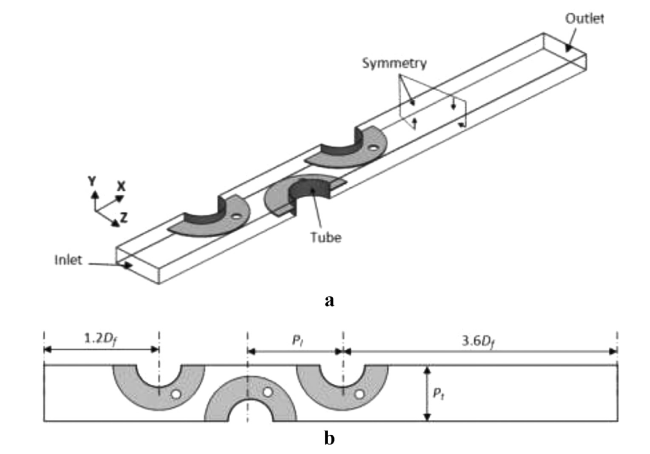
Fig. 2. Computational domain: (a) Geometry with the boundary conditions adopted; (b) A view from the top of the computational domain. |
As in other studies [17,21,29], the upstream boundary is positioned at 1.2 times the fin diameter from the center of the first row to ensure a uniform velocity distribution. Due to the pressure condition, the downstream boundary is set as 3.6 times of the fin diameter from the last row center to allow the flow development.
The Reynolds number, which is based on the outside diameter of the fin collar tube Dc (Dc = Dt + 2 tf) and the maximum velocity at the minimum free flow area, ranges from 4300 to 15,000. At this range of Re, the flow is considered three-dimensional, incompressible, steady-state, and turbulent [39,40].
2.2. Materials and methods
2.2.1. Governing equations
Continuity equation:
$\frac{\partial {{u}_{i}}}{\partial {{x}_{i}}}=0$
Momentum equation:
$\frac{\partial }{\partial {{x}_{j}}}\left( \rho {{u}_{i}}{{u}_{j}}+p{{\delta }_{ij}}-\mu \left( \frac{\partial {{u}_{i}}}{\partial {{x}_{j}}}+\frac{\partial {{u}_{j}}}{\partial {{x}_{i}}}-\frac{2}{3}{{\partial }_{ij}}\frac{\partial {{u}_{l}}}{\partial {{x}_{l}}} \right)+\rho \overline{u_{i}^{,}u_{j}^{,}} \right)=0$
The Reynolds stress tensor, using the Boussinesq approximation, is:
$-\rho \overline{u_{i}^{,}u_{j}^{,}}={{\mu }_{t}}\left( \frac{\partial {{u}_{i}}}{\partial {{x}_{j}}}+\frac{\partial {{u}_{j}}}{\partial {{x}_{i}}} \right)-\frac{2}{3}\left( \rho k+{{\mu }_{t}}\frac{\partial {{u}_{i}}}{\partial {{x}_{i}}} \right){{\delta }_{ij}}$
Steady-state computations were achieved with the RNG k-ԑturbulent model. This model is based on the following transport equations:
$\rho {{u}_{i}}\frac{\partial k}{\partial {{x}_{i}}}=\frac{\partial }{\partial {{x}_{i}}}\left( {{\alpha }_{p}}\left( \mu +{{\mu }_{t}} \right)\frac{\partial k}{\partial {{x}_{i}}} \right)+{{\mu }_{t}}{{S}^{2}}-\rho \varepsilon $
$\rho {{u}_{i}}\frac{\partial \varepsilon }{\partial {{x}_{i}}}=\frac{\partial }{\partial {{x}_{i}}}\left( {{\alpha }_{p}}\left( \mu +{{\mu }_{t}} \right)\frac{\partial \varepsilon }{\partial {{x}_{i}}} \right)+{{C}_{1\varepsilon }}\frac{\varepsilon }{k}{{\mu }_{t}}{{S}^{^{2}}}-{{C}_{2\varepsilon }}\rho \frac{{{\varepsilon }^{2}}}{k}-R$
In these equations, k and ԑ are the turbulent kinetic energy and the dissipation rate of k, respectively. αp = 1.42 presents the inverse Prandtl number. R and S are the rate of strain term and the modulus of the rate of the strain tensor, respectively. The RNG theory gives the values of the constants C1ԑ = 1.42 and C2ԑ = 1.68.
Energy Equation:
$\frac{\partial \left( {{u}_{i}}\left( \rho E+p \right) \right)}{\partial {{x}_{i}}}=\frac{\partial }{\partial {{x}_{i}}}\left( \left( {{k}_{a}}+{{k}_{t}} \right)\frac{\partial T}{\partial {{x}_{i}}} \right)$
where, E is the total energy, ka is the air conductivity, and kt is the turbulent thermal conductivity.
The solved energy equation in the solid region is:
$\frac{\partial }{\partial {{x}_{i}}}\left( {{k}_{al}}\frac{\partial T}{\partial {{x}_{i}}} \right)=0$
2.2.2. Boundary conditions
The boundary conditions illustrated in Fig. 2 are as follows:
1) Inlet conditions: dry air at a temperature of 292 K enters the calculation domain with a uniform velocity uin and turbulent intensity I (5%).
2) Outlet conditions: a static pressure is set at the exit of the geometry.
3) At the tube surface: A constant temperature of Tt = 353 K and zero velocity are applied on the tube surface.
4) At the fin surface: No-slip conditions for the velocity are set. The temperatures on the fins are calculated by solving the conjugated conduction-convection of the heat transfer problem Eqs. (1)-(7).
5) At the symmetry planes: The temperature gradients and tangential components of the velocity gradients in the vertical direction are set to zero, i.e., no convective flux occurs across the symmetry plane.
2.3. Numerical prediction
The pre-processor GAMBIT was employed to realize the geometry and computational grids. Non-uniform grids with fine mesh sizes were generated in zones near the solid-fluid interphase, where the high gradients of velocities and temperature are expected (Fig. 3). However, the coarse mesh sizes were applied for the extension domains. Before examining the impact of fin designs and fin spacing on overall efficiency, some grid independence tests were achieved to improve the accuracy of the computed results. These tests were carried out for perforated and star-shaped fins. The number of grid elements was varied between 1.2 million and 4.4 million cells with fin spacing of 2 and 7 mm and at uin = 3.7 m/s. When the number of cells varied between 3.4million and 4.4 million cells, the friction factor was changed by less than 3% and the Colburn factor was changed by less than 2% (Table 2). Hence, a grid of 2.6 million to 3.4 million cells (depending on the fin spacing and fin design) was selected. We note that the average value of y+ was below 5 for all of the cases considered.
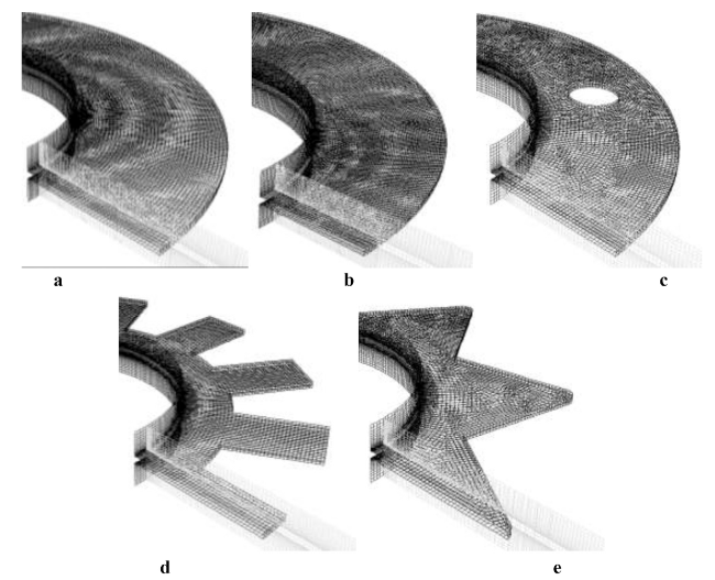
Fig. 3. Grid generations for: (a) concentric circular fin; (b) eccentric circular fin; (c) perforated circular fin; (d) serrated circular fin; (e) star-shaped fin. |
Table 2. Results of the grid independence tests. |
| Fin type | Star-shaped fin | Perforated fin | |||||||||
|---|---|---|---|---|---|---|---|---|---|---|---|
| Number of cells | 1.2 × 10⁶ | 1.9 × 10⁶ | 2.6 × 10⁶ | 3.4 × 10⁶ | 4.4 × 10⁶ | 1.2 × 10⁶ | 1.9 × 10⁶ | 2.6 × 10⁶ | 3.4 × 10⁶ | 4.4 × 10⁶ | |
| j | S = 2 mm | 0.0091 | 0.0082 | 0.0078 | 0.0078 | 0.0078 | 0.008 | 0.0076 | 0.0073 | 0.0073 | 0.0072 |
| S = 7 mm | 0.011 | 0.0101 | 0.0094 | 0.0089 | 0.0089 | 0.0097 | 0.009 | 0.0084 | 0.0079 | 0.0078 | |
| f | S = 2 mm | 0.3223 | 0.278 | 0.2466 | 0.2396 | 0.2365 | 0.2801 | 0.2594 | 0.2402 | 0.2371 | 0.2347 |
| S = 7 mm | 0.1435 | 0.1105 | 0.0992 | 0.0878 | 0.0871 | 0.1245 | 0.103 | 0.0946 | 0.087 | 0.0861 | |
Recently, several methods have been used by researchers to solve nonlinear equations of physics problems, such as the Chun-Hui He's iteration method [41], the Ancient Chinese Algorithms [42], and the Poincaré-Lindstedt technique [43]. Also, several techniques have been applied by the researchers on the oscillation theory of different orders of differential equations [44], [45], [46], [47], [48], [49]. As the majority of engineering problems are formulated as differential equations, therefore the numerical approaches become an effective tool in the solving of several thermo-hydraulic problems such as flow-induced by rotating objects [50], Jeffrey fluid with Prabhakar fractional derivative [51], Magnetohydrodynamics flow [52], and non-Newtonian fluids flow [53], [54], [55]. However, for the case of conjugate conduction-convection of heat transfer problems in combination with turbulent flow, the finite-volume method (FVM) based commercial solver ANSYS-Fluent is the most suitable in solving this problem types [1], [2], [3], [7], [8],[17], [18], [19]. Thus, the CFD software FLUENT was utilized to achieve the computations. The second-order upwind numerical scheme and PISO algorithm are applied to discretize the governing equations Eqs. (1)-(7). The selected convergence criteria were10−6 for energy and 10−4 for the velocity (x, y, z), continuity, k, and ε. Eqn (10)-18
2.4. Data reduction
The rate of the convective thermal exchange on the air-side of the finned tube bundle was calculated according to Eq. (8).
$Q=\dot{m}{{c}_{p}}\left( {{T}_{out}}-{{T}_{in}} \right)$
where $\dot{m}=\rho {{A}_{in}}{{u}_{in}}$ is the mass flow rate of the air.
The convective thermal exchange coefficient may be calculated using the following expression:
$h=\frac{Q}{\left( {{A}_{t}}+\eta {{A}_{f}} \right). \Delta {{T}_{LMTD}}}$
where the thermal exchange coefficients at the walls of the base tube and fin are considered to be the same, At is the tube surface area, Af is the total fin surface area,ηis the fin efficiency and $ \Delta {{T}_{LMTD}}$ is the logarithmic mean temperature difference and is given by,
$ \Delta {{T}_{LMTD}}=\frac{{{T}_{out}}-{{T}_{in}}}{\ln \frac{\left( {{T}_{t}}-{{T}_{in}} \right)}{\left( {{T}_{t}}-{{T}_{out}} \right)}}$
$\eta =\frac{\int \left( {{T}_{f}}-{{T}_{a}} \right)dA}{\int \left( {{T}_{t}}-{{T}_{a}} \right)dA}$
Here, Tais the average temperature of the ambient air calculated separately at every finned-tube row and Tt is the tube base temperature.
The hydrothermal characteristics are written in dimensionless form as:
$Re=\frac{{{\rho }_{a}}{{u}_{\max }}{{D}_{c}}}{{{\mu }_{a}}}$
$Nu=\frac{h{{D}_{c}}}{{{k}_{a}}}$
$j=\frac{Nu}{Re\text{ }P{{r}^{1/3}}}$
$f=\frac{ \Delta P}{\frac{1}{2}{{\rho }_{a}}u_{\max }^{2}}\frac{{{D}_{c}}}{L}$
where, Lis the length of the array.
${{P}_{EC}}=Nu.{{f}^{-1/3}}$
In the present study, a global performance criterion GPC is also used to determine the comprehensive efficiency of the heat exchanger with a given volume. It is defined as the gain in the thermal exchange rate from bundles per unit power consumption [39]:
${{G}_{PC}}=\frac{Q}{ \Delta P\dot{V}}$
where $\dot{V}$ is the volumetric flow rate and Q is the total thermal exchange.
The mass global performance criterion ${{M}_{{{G}_{PC}}}}$ determines the global performance criterion with a given mass of a finned-tube bundle. The most significant amount ofMGPC indicates that a given finned-tube design is optimum from a thermal-flow viewpoint performance and material requirement. It is defined as:
${{M}_{{{G}_{PC}}}}=\frac{Q}{ \Delta P\dot{V}}\frac{{{M}_{f.f}}}{{{M}_{f}}}={{G}_{PC}}\frac{{{M}_{f.f}}}{{{M}_{f}}}$
Here, ${{M}_{f.f}}$ is the mass of the full fin (such as concentric and eccentric fins) and Mf is the mass of the considered fin.
3. Validation of the numerical model
In our previous works [11,12], the validation for the concentric and eccentric circular finned-tube has been conducted by comparing numerical results with the experimental findings of Chen et al. [58]. In the present paper, the validation is performed for perforated, serrated, and star-shaped fins. For the 2-hole perforated fin, the results of our CFD simulations are compared with those provided experimentally by Lee et al. [16]. However, the serrated circular finned-tube findings are compared with those of Ma et al. [59] for the geometry bank 4. Our numerical results for the star-shaped fin have been compared with the published results of Bošnjaković et al. [26].
Table 3. Validation of the numerical results for perforated, serrated, and star-shaped fins. |
| Perforated fin | Serrated fin | Star-shaped fin | ||||||
|---|---|---|---|---|---|---|---|---|
| uin(m/s) | h(W/m2K) [16] | h(W/m2K)(Present work) | ${{\operatorname{Re}}_{{{D}_{t}}}}$ | j/f [52] | j/f(Present work) | uin(m/s) | Nu [26] | Nu(Present work) |
| 4 | 81.01 | 79.32 | 7500 | 105.4 | 106.08 | 1.7 | 37.1 | 37.85 |
| 13,500 | 102.2 | 104.6 | 3.7 | 69.1 | 72.32 | |||
| 20,000 | 97.4 | 101.32 | 5.9 | 81.7 | 85.37 | |||
4. Results and analysis
4. 1. Flow characteristics
The convective heat transfer and pressure loss characteristics along with the direction of airflow are related to the flow configuration around it. The shape and size of the recirculation zone behind the tubes and the thickness of the boundary layer vary with the profile of fins. In fact, the reverse flows behind the tubes (wake region) result in poor heat transfer.
The velocity vectors near the fins and behind the tubes of the first rows for different fin configurations are illustrated in Fig. 4 for the fin spacing S = 5 mm and Re = 9400. A zone with weak velocities is observed behind the tubes for all the fins. However, the size of this recirculation zone between the concentric circular finned-tube CCFT (Fig. 4a) is larger than that for the other fin shapes. In the case of ECFT (Fig. 4b) and PCFT (Fig. 4e), the recirculation zone becomes narrow, and the wake vortex generated in these cases is moved to the fin tip. The perforations altered the velocity gradients, and the flow velocity is increased slightly in the downstream region of the finned tubes due to the holes (Fig. 4e). Consequently, the size of these vortices became significant.
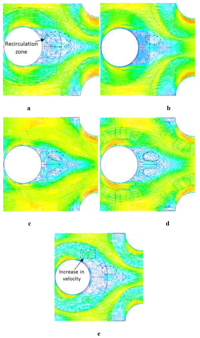
Fig. 4. Velocity vectors for: (a) Concentric circular fin; (b) Eccentric circular fin; (c) Star-shaped fin; (d) Serrated circular fin; (e) Perforated circular fin. |
From serrated circular finned-tube SCFT and star-shaped finned-tube S-SFT (Figs. 4c and 4d, respectively), the recirculation zone is disturbed by the more intense interruption of fins. On the other hand, the comparison of the recirculation flow generated by SCFT and S-SFT and by concentric circular finned-tube CCFT (Fig. 4a) revealed that for CCFT the flow recirculation zone occupies the majority of the rear part of the fin. However, in the case of SCFT and S-SFT, the mean flow is highly turbulent at the fin tip with low velocities between the fin segments.
The temperature distribution in the middle of the fin thickness is shown in Fig. 5 for all fin geometries. The considered geometries have the same outer fin diameter. The analysis of these temperature fields indicates the existence of temperature gradients along with the longitudinal flow direction of ECFT. These temperature gradients are greater than those of the other fin configurations, which suggests that a significant global thermal exchange occurs for this type of fins for a fixed Reynolds number. This is due to the decrease in the recirculation loop behind the tube. Although the holes in the case of PCFT reduce the thermal exchange area, the temperature gradient along the flow direction is noticeably larger than that for the CCFT. This might be because the perforated fins interrupt the growth of the boundary layer and increase the fluid mixing in the recirculation zone.
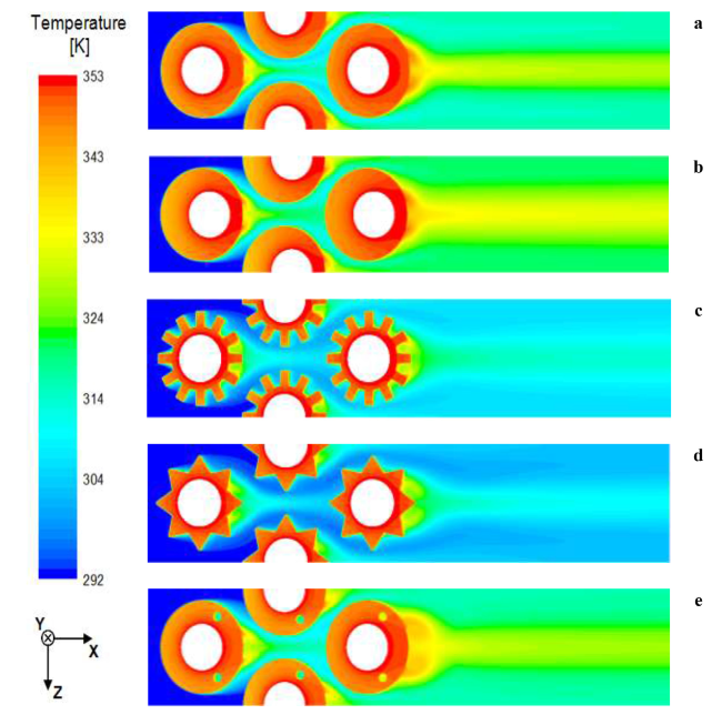
Fig. 5. Temperature contours in the middle of the fin thickness: (a) Concentric circular fin; (b) Eccentric circular fin; (c) Star-shaped fin; (d) Serrated circular fin; (e) Perforated circular fin. |
For the conventional CCFT, the comparison between SCFT, S-SFT in terms of temperature distribution revealed the existence of small temperature gradients along the longitudinal flow direction for both SCFT and S-SFT configurations. This is because the SCFT and S-SFT can have up to 41.42% less surface area compared with the conventional CCFT. The temperature gradient downstream the fins is lower than that upstream, which is due to the recirculation zone behind the tubes. In addition, a significant temperature gradient is present in the second row for all cases (Fig. 5), which is due to the high impinging velocity at the second row of the staggering array [7].
4.2. Influence of the fin design
For Re varying from 4300 to 15,000 and at a fixed fin spacing (S = 5 mm), the hydrothermal efficiency is presented and compared in this section for five fin geometries.
The results of convective heat transfer coefficient h are plotted in Fig. 6 versus Reynolds number for each fin design. For all fin shapes, h augments strongly with Re due to the significant thermal exchange rate at high velocity. The convective thermal exchange coefficient of CCFT is lower than that for the other fin designs in the whole range of Re. Besides, the difference in the convective thermal exchange coefficient between the fins increases with the rise of Re.
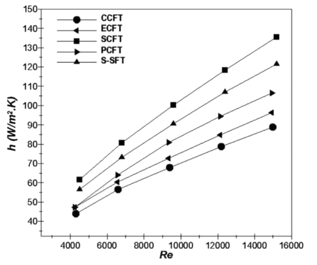
Fig. 6. Effect of the fin design on heat transfer coefficient at different Reynolds numbers. |
The serrated circular finned-tube (SCFT) outperforms the other fin geometries at all the corresponding values of Reynolds number. The amount of h for the SCFT is considered to be 40.3-52.3% higher than that for the conventional CCFT and about 26.2-31.7% higher than that for the PCFT, depending on Reynolds number.
Similarly, the S-SFT and PCFT fins provide a higher thermal exchange coefficient than the concentric circular finned-tube (CCFT) by about 28.6-37.5% and 8-19.8%, respectively. This is due to their tendency to interrupt the boundary layer and intensify the fluid mixing. Furthermore, the comparison between ECFT and CCFT reveals that the ECFT produces a thermal exchange coefficient greater by around7.1-8.3%. The main reason is the decreased size of the inactive thermal exchange areas (dead regions) in the case of ECFT. These results confirm the findings of Lemouedda et al. [21], Bošnjaković et al. [26], Lee et al. [16], and Benmachiche et al. [12] that the convective heat transfer for SCFT, S-SFT, PCFT and ECFT is higher compared with the CCFT.
It is always important to explore the hydrothermal behavior in dimensionless numbers. Thus, the Colburn factor and friction factor are presented in Figs. 7 and 8, respectively. The value of j is reduced by 15-25% with the rise of Re (Fig. 7). Similarly to the convective thermal exchange coefficient, j is the greatest for the SCFT and the lowest for the CCFT. The cause is the same as that for h in Fig. 6. Moreover, the difference in the values of Colburn factor between all the fins becomes considerable with increased Reynolds number.
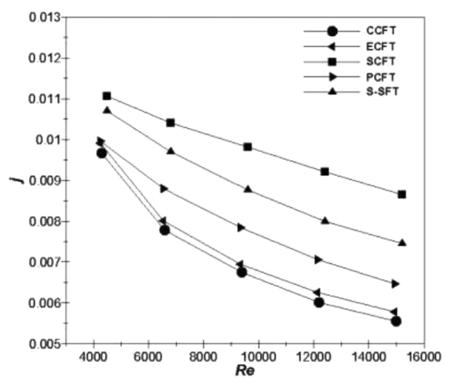
Fig. 7. Effect of the fin design on Colburn factor at different Reynolds numbers. |
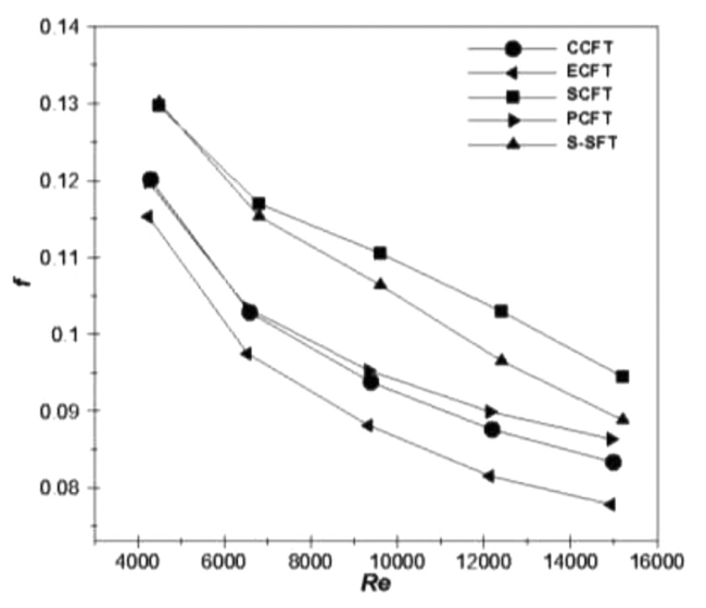
Fig. 8. Effect of fin design on friction factor at different Reynolds numbers. |
The lowest pumping power to overcome the losses of pressure and ensure the fluid movement through the finned-tube bundle is required to choose the fin geometry. Therefore, Fig. 8 shows the friction factor f for all of the inspected shapes of fins at various Re. The increased Re yields a decrease in f values for all the fin cases. As Re augments, the maximum velocity and the pressure drop are increased as well. However, and due to the dependence of f with the ratio of the pressure drop to the square of the maximum velocity (Eq. (15)), the resulting f decreases. We can observe that SCFT and S-SFT provide, respectively, 8-13.4and 6.6-8.4% higher friction factors than the CCFT. This might be because the segments in SCFT and S-SFT generate a considerable disturbance of the flow and pressure drop. The f values for CCFT are lower than those of PCFT for all Re. The largest difference in f amounts is observed at higher Re, where it is estimated to be about 4% for PCFT above the geometry CCFT. However, f of the eccentric circular finned-tube (ECFT) is lower than the other fin shapes. The friction factor for ECFT is lower than that for CCFT by around 4.1-7.2% because ECFT has about 32% less flow recirculation surface (dead region) than the CCFT.
The fin efficiency, which is required for the evaluation of the thermal exchange coefficient (Eq. (9)), is plotted in Fig. 9 vs. Re for all the fin configurations. As observed, the fin shape and Reynolds number directly impact fin performance. For all cases, the fin performance decreases considerably with increasing Re due to the enhanced convection. In addition, the CCFT provides 9.1-15% higher fin efficiency as compared with the other fin patterns. For all Reynolds numbers, the SCFT and S-SFT provide lower fin efficiency due to their segmented shapes. However, the conventional CCFT yields higher fin efficiency than that of the ECFT. The CCFT offers 1.5-2.1% and 1.5-3.5% higher fin efficiency than those for the ECFT and PCFT, respectively. These findings agree well with the previous numerical data of Chen and Hsu [58], Bošnjakovićet al [25], Tahrour et al. [11], and Unger et al. [30].
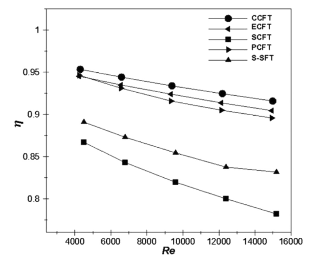
Fig. 9. Effect of the fin design on its efficiency at different Reynolds numbers. |
4.3. Impact of the fin spacing
The fin spacing was changed from 2 to 7 mm to inspect the impact of this parameter. The inlet air velocity has been kept constant for all fin designs at uin = 3.7 m/s Fig. 10 illustrates the thermal exchange coefficient vs. the fin spacing for all the fin geometries. As highlighted, the serrated circular finned-tube (SCFT) outperforms the other fin designs for any value of the fin spacing. We can also observe that h increases by 5.8-11.8% in the range of S = 2 to 5 mm.ForS> 5 mm, the thermal exchange coefficient remains almost constant with a slight tendency to increase (by about 1.3%). Mon and Gross [3] also found that, in the case of CCFT, the thermal exchange coefficient increases in the range of S/hf = 0.07 to 0.32, and then, it remains almost constant. The experimental studies of Kuntysh et al. [60] and Watel et al. [61] showed that if the fin spacing exceeds about twice the boundary layer thickness at the base of the fin, the impact of the fin spacing on the convective thermal exchange coefficient is negligible. Therefore, the present computed findings for the staggering array confirm that the fin spacing value largely affects the thermal exchange coefficient. Further details on the impact of the fin spacing on the thermal boundary layer may be found in Ref [11].
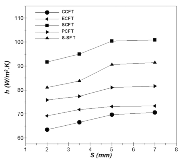
Fig. 10. Influence of the fin spacing on heat transfer coefficient, at uin = 3.7 m/s. |
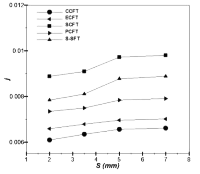
Fig. 11. Influence of the fin spacing on Colburn factor, at uin = 3.7 m/s. |
The impact of the fin spacing on the friction factor is depicted in Fig. 12 at a particular inlet air velocity of uin = 3.7 m/s. For all the fin designs, the friction factor decreases with the rise of S. When S is changed from 2 to 7 mm, the friction factor is reduced by 64.8 and 61.6% for SCFT and ECFT, respectively, which is due to the reduction of the strong interaction between the boundary layers. With increasing fin spacing, the SCFT and S-SFT provide, respectively, about 7.7-12.4% and 3.3-6.1% higher friction factor than that of the CCFT. On the other hand, the value of f for the ECFT is lower than that for the other fin shapes in the whole range of fin spacing. Precisely, it is lower by about 6.7 to 11% than that for the CCFT.
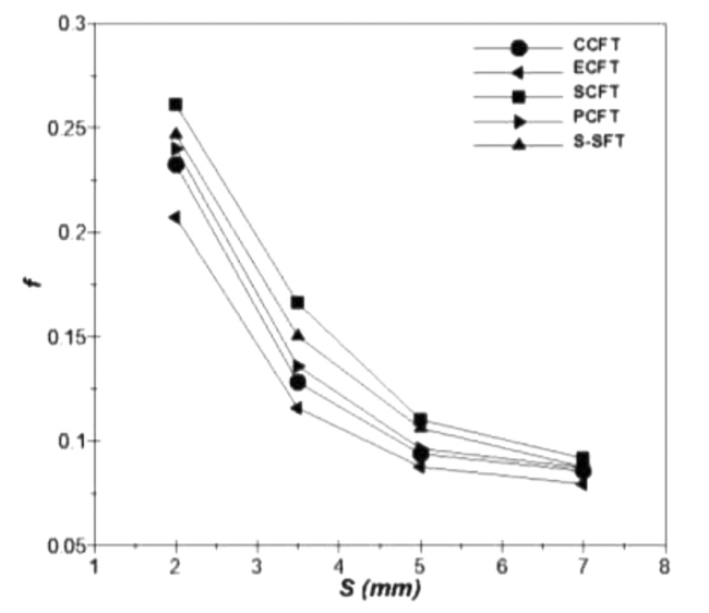
Fig. 12. Influence of the fin spacing on the friction factor, at uin = 3.7 m/s. |
In Fig. 13, the fin efficiency (η) is illustrated for various fin shapes and spacing. A reduction of η is observed with increasing S for all shapes of the fins. These results agree well with the findings in the literature [29,30]. The thermal exchange rate is enhanced at large fin spacing, and consequently, the temperature gradient along with the fin is reduced. The concentric circular fin provides 1.3-18% higher fin efficiency than those of the other fin geometries when rising S from 2 to 7 mm. Furthermore, the SCFT has the lowest fin efficiency from all examined fin shapes due to the effect of serration, which increases the convective thermal exchange and enhances the cooling of the fin.
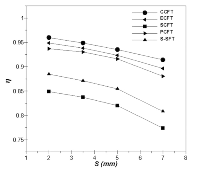
Fig. 13. Influence of the fin spacing on the fin efficiency, at uin = 3.7 m/s. |
According to the basic design of finned tubes, a required total thermal exchange area must be realized without reducing the thermal exchange rate and increasing the pressure losses. Therefore, the performance evaluation criterion PEC [57,62], the global performance criterion GPC [39,62], and for the first time, the mass global performance criterion ${{M}_{{{G}_{PC}}}}$ are used to determine the optimum fin shape. The definition of the overall performances is a key parameter in designing heat exchangers [63], [64].
The performance evaluation criterion PEC is displayed in Fig. 14 for different fin shapes, Reynolds numbers, and at a fin spacing of S = 5 mm. Whatever the shape of fins, PEC is increasing with the rise of Re due to the augmentation of the convective thermal exchange coefficient and the decrease in the friction factor. The SCFT provides higher PEC than the other fin shapes, estimated to be 9.2, 22.9, and 46.2% higher than that for S-SFT, PCFT, and CCFT, respectively at Re = 15,000. The induced flow mixing due to the segments of SCFT and S-SFT improves the convective thermal exchange more intensely than the pressure, and thus, PEC becomes significant. However, the performance evaluation criterion of CCFT is lower than that for the other fin geometries regardless of the Re value. In addition, the difference in PEC between the fins decreases with decreasing Re. Finally, when the thermal exchange surface and the pressure losses are relevant, SCFT gives the highest thermal-flow efficiency.
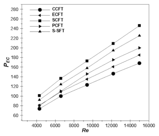
Fig. 14. Influence of the fin shape and Reynolds number on the performance evaluation criterion, at S = 5 mm. |
Fig. 15 shows the variation of the global performance criterion (GPC) vs. Re for various fin geometries. Whatever the shape of the fin, GPC decreases with the rise of Re, since the pumping power increases highly in combination with the slow increase of heat transfer rate. From all of the fins investigated, the GPC provided by ECFT is the most significant, which is higher by about 9.3-12.7 and 20.3-28.3%than those of the CCFT and SCFT, respectively. Two reasons can explain this: (1) ECFT has the largest surface area of the upstream region (active region) compared with the other fins, and (2) ECFT has about 32% less enlarged dead region behind the tube than that of the CCFT. However, GPC of the ECFT decreases with the increasing Re until Re > 12,000, where the difference is not noticeable. Also, since SCFT has about 36% less surface than the full fins (CCFT or ECFT), the heat transfer rate is lower, and consequently, GPC will decrease, and it is almost the same as that for S-SFT. Finally, PCFT and CCFT reveal almost the same global performance criterion since the improvement of the thermal exchange by holes is associated with the augmentation in pressure losses (Fig. 12).
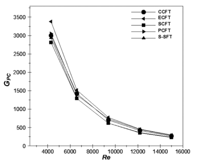
Fig. 15. Influence of the fin shape and Reynolds number on the global performance criterion, at S = 5 mm. |
Note that the performance evaluation criterion PEC and the global performance criterion GPC represent only the thermal exchange capacity with a given flow resistance. However, the material costs and the weight of the finned-tube bundle are essential for industrial applications. So, the mass global performance criterion ${{M}_{{{G}_{PC}}}}$ was inspected to make a good choice of the fin shape.
Fig. 16 shows the ${{M}_{{{G}_{PC}}}}$ versus Reynolds number for different fin shapes. As observed, ${{M}_{{{G}_{PC}}}}$ decreases with the rise of Re for all of the fin shapes. At low Re, the difference in ${{M}_{{{G}_{PC}}}}$ between the fins is considerable due to the significant thickness of the boundary layer, which consequently enhances the thermal effect of the newly designed fins. Also, it should be noted that the ${{M}_{{{G}_{PC}}}}$ values are the same as GPC in the case of CCFT and ECFT. In contrast to the global performance criterion, S-SFT and SCFT provides the highest ${{M}_{{{G}_{PC}}}}$ as compared with the full fins of CCFT (41–73% higher) and ECFT (29–54% higher). This is because the mass of S-SFT and SCFT is lower by 43.4 and 39.7%, respectively, than the full fin (CCFT and ECFT). Furthermore, S-SFT provides the highest ${{M}_{{{G}_{PC}}}}$ values at all Re.
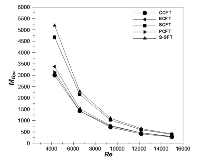
Fig. 16. Influence of the fin shape and Reynolds number on the mass global performance criterion, at S = 5 mm. |
As expected, the mass global performance criterion of ECFT is higher by around 9.3 to 12.5% than that of CCFT depending on Re, which is due to the lower GPC for CCFT compared with the ECFT. Furthermore, the difference between PCFT and CCFT is slight since these two fins global performance criterion and mass requirement are almost the same. In general, PCFT provides a ${{M}_{{{G}_{PC}}}}$ alue that is higher by 4.4–7.4% than the conventional CCFT. In conclusion, the optimum fin design should be determined by considering both the thermal-hydraulic efficiency and mass requirement of the finned-tube bundles, which will be helpful for the geometric optimization of thermal devices. Thus, based on the mass global performance criterion ${{M}_{{{G}_{PC}}}}$, the star-shaped finned-tube (S-SFT) performs better than the other geometries.
5. Conclusions
In this paper, various fin patterns (concentric, eccentric, perforated, serrated, and star-shaped fins), which are applied in several offshore energy systems, have been explored numerically. The findings were provided and compared in terms of thermal-hydraulic performances such as PEC, GPC, and ${{M}_{{{G}_{PC}}}}$ vs. Re number. The effects of fin design and spacing on the hydrothermal behavior were examined for a range of Re (4300–15,000). From the analysis of the parameters examined, the following main findings may be drawn:
• For all newly designed fins, the Colburn factor (j) is higher than that of the conventional CCFT, whereas the SCFT provides the most significant value.
• SCFT produces the highest friction factor at all fin spacing (7.7-12.4% higher than that of the CCFT). However, the friction factor of ECFT is lower than that for the other fin designs in the whole range of fin spacing and at uin = 3.7 m/s.
• An increase in the thermal exchange coefficient and Colburn factor was observed with the rise of S up to S = 5 mm, and then, they remained almost constant. But the friction factor and the fin performances were reduced with increasing fin spacing.
• In terms of performance evaluation criterion PEC, all the newly designed fins performed better than the conventional CCFT and SCFT reached the highest PEC values, which is estimated to be 9.2, 22.9, and 46.2% higher than that for S-SFT, PCFT, and CCFT, respectively at Re = 15,000. Also, whatever the shape of fins, PEC increases with the rise of Re.
• The tubes with eccentric fins outdo all the fin patterns in terms of the global performance criterion, which is higher by about 9.3-12.7 and 20.3-28.3%than those of the CCFT and SCFT, respectively. However, the values of the global performance criterion are almost identical for CCFT, PCFT, SCFT, and S-SFT.
• In terms of the mass global performance criterion ${{M}_{{{G}_{PC}}}}$, heat exchanger with S-SFT and SCFT provides the highest ${{M}_{{{G}_{PC}}}}$ as compared with the full fins of CCFT (41–73% higher) and ECFT (29–54% higher). Nevertheless, S-SFT outperforms all examined fin designs at all Reynolds numbers. Therefore, a heat exchanger with star-shaped fins is recommended to be used to cool offshore and onshore power generation systems.
Declaration of Competing Interest
The authors declare that they have no known competing financial interests or personal relationships that could have appeared to influence the work reported in this paper.
