
1. Introduction
In recent years, under the background of ‘carbon neutral’ and high proportion of renewable energy development strategy, renewable energy has become the leading role of the third energy conversion. The wind energy industry is increasingly becoming the focus of attention as one of the most important renewable energy sources [1]. The interest of researchers in the offshore wind turbine as a promising wind energy exploitation device is growing up [2,3]. Offshore wind turbine support platforms can be divided into fixed-type and floating-type according to structural characteristics, where fixed-type platforms are generally used in shallow waters and floating-type platforms are used in deep waters. As the cost of floating offshore wind turbine (FOWT) decreases, the development of FOWT into shallow waters is gradually becoming possible [4]. Floating-type platforms are divided into four main types according to the mechanism of obtaining stability [5,6]: barge type, semi-submersible type, TLP (Tension Leg Platform) type and spar type, as shown in Table 1.
Table 1. Typical floating-type platforms. |
| Type | Barge | Semi-Submersible | TLP | SPAR |
| Schematic diagram |  |  |  | 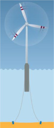 |
| Mechanism of obtaining stability | Large waterplane area | Multiple small waterplane area with large intervals | Multiple pre-tensioned legs with large intervals | Deep draft and CG below CB |
| Water depth suitability | Operable at depths starting 30 m | Depth independence | Having a good water-depth flexibility | Deep drafts and large seabed footprint |
| Suitability of mooring system for shallow water | Demanding more robust mooring systems | Cheap and simple mooring system | Complex and costly mooring system | Cheap and simple mooring system |
The barge type floating foundation provides sufficient restoring moment mainly through the larger waterplane area of the platform, thus maintaining the stability of the structure. Lefranc and Torud [7] conducted a related study on the structural form of the foundation of the barge type. It is found that the shallow draft and large waterline surface area of the barge type structure led to large wave loads and large motion responses of the wind turbine, so it is not suitable for the severe sea environment. Therefore, barge type FOWTs are relatively rare.
The TLP floating foundation is directly connected to the seabed by pre-tensioned vertical tension legs, which makes the motion of the platform nearly rigid, thus making the platform have relatively good stability. The typical TLP wind turbine concepts include Blue H TLP [8], GICON-TLP [9], DTU-TLP [10] and Star TLP [11] et al. In general, the TLP floating foundation is suitable for deep waters, its mooring system structure and installation process are comparatively complicated, and the partial failure of the tension legs will also lead to catastrophic consequences.
The semi-submersible floating foundation with a large spacing between each column and a large waterplane area of the columns provides the platform with the required restoring moment and maintains good stability [12]. At the same time, its draft is small and suitable for relatively shallow water depth. The typical semi-submersible wind turbine concepts include WindFloat [13], Fukushima-Forward [14], et al. However, the column diameter of semi-submersible floating foundations is usually relatively large, resulting in higher wave loads, and good hydrodynamic performance requires a larger displacement capacity.
As for the spar type floating foundation, it reduces the center of gravity by ballasting in the lower part of the spar, so that the CG is sufficiently lower than the center of buoyancy (CB) to ensure the stability of the system. The typical spar type wind turbine concepts include Hywind [15], OC3-Hywind [16] and Spar Torus Combination (STC) [17], et al. However, the spar type floating foundation has a larger draft, generally more than 100 m, therefore it is mainly suitable for deep water area.
Due to the shortage of several classical floating foundations, the intent of this research study is to provide and validate a multi-column platform concept with low CG that combines the advantages of semi-submersible floating foundation and spar type floating foundation, as shown in Fig. 1. The multi-column low CG platform is designed to support a 6MW wind turbine class [18] and operate at a water depth of 50m in the South China Sea. The concept of the multi-column low CG platform (multi-column deep-draft platform) has a deeper draft than a typical semi-submersible floating foundation. The CB of the platform is increased by using large diameter cylindrical cross braces below the still water line (SWL), which providing a certain buoyancy, thus reducing the diameter of the offset columns (can be regarded as a short SPAR). In addition, the CG of the platform is lowered by using large diameter base columns as ballast tanks, and the bottom ballast also effectively increases the heave damping. With the above changes, the CG of the multi-column deep-draft platform concept is much lower than the CB, which satisfies the stability requirement of the platform and solves the disadvantage that the SPAR platform cannot be applied in shallow water. To verify the viability of the multi-column deep-draft platform, the coupled dynamic responses of the FOWT system are simulated by the time domain software FAST [19] and the frequency domain software WADAM [20]. In addition, the effect of the second-order wave force may increase with the decreasing of water depth, because a lower water depth is usually associated to a lower natural period [21,22]. Thus, the effect of second-order wave load is considered in the simulation model and the results are compared and analyzed. Statistical values and spectral analysis are performed for motion response of the multi-column platform, fore-aft force and moment of the tower base and mooring force are researched respectively. The results demonstrate that the coupled dynamic responses at rated operating condition and extreme condition meet the normal operating requirements and extreme survival requirements of FOWT system in the shallow water of South China Sea. In addition, it is found that, the wave frequency response gradually replaces the second-order low frequency response as the main influencing factor of the coupled dynamic response of the FOWT system with the increasing severity of the sea states. However, in general, the magnitude of second-order low frequency response increase with the increasing severity of the design load cases. Thus, in the subsequent design of the shallow water FOWT system, the second-order effects should be paid enough attention.
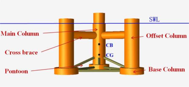
Fig. 1. Multi-column low CG floating platform |
The remaining part of the paper is organized as follows. Details of multi-column low CG FOWT concept are represented in Section 2. Section 3 introduces the parameter settings of the numerical simulation model. Reference site and environmental conditions of the simulation are described in Section 4. The simulation results are compared and analyzed in Section 5 for different design load conditions. Finally, in Section 6 some conclusions are drawn.
2. Multi-column FOWT with low CG concept design
The multi-column low CG FOWT system is designed to support a 6MW wind turbine class and installed at 50m water depth. The FOWT system is equipped with three main components: a 6MW wind turbine, a multi-column deep-draft platform and a mooring system, as shown in Fig. 2.

Fig. 2. Multi-column floating wind turbine system with low CG |
2.1. Wind turbine
The wind turbine system is the critical part of a FOWT for energy conversion. Thus, wind turbine system is the primary consideration in the FOWT design process. In this paper, a 6MW class wind turbine system is used for the FOWT. The wind turbine system is composed of three main parts: nacelle, blades and hub. The tower is mainly used to connect the upper wind turbine and the multi-column platform. The main properties of the wind turbine are listed in Table 2. Detailed parameters of the 6MW wind turbine system could be referred to [23,24].
Table 2. Main characteristics of wind turbine. |
| Wind turbine | Unit | Value |
| Rated power | MW | 6 |
| Rotor orientation | Upwind,3 Blades | |
| Blade length | m | 78 |
| Hub radius | m | 2.35 |
| Hub center height | m | 100 |
| Cut-in, Rated, Cut-out Wind Speed | m/s | 3,10.5,25 |
| Rated rotor speed | rpm | 10 |
| Blade mass | kg | 29196 |
| Tower mass | kg | 409822.7 |
| Nacelle mass + rotor mass | kg | 230000 |
2.2. Multi-column deep-draft platform
The supporting multi-column deep-draft foundation concept is designed for water depth of 50m with low CG. The multi-column deep-draft foundation is the major difference between the floating wind turbine concept in this paper and the semi-submersible wind turbine. The multi-column deep-draft foundation is consisted of five parts: main column, cross braces, offset columns, base columns and pontoons, as shown in Fig. 1.
In the concept of the multi-column deep-draft foundation, large diameter cylindrical cross braces are used to connect the main column with the offset columns. The cross braces are located below the SWL, thus providing a certain buoyancy, allowing the overall buoyancy of the platform to move upward and reducing the displacement volume requirement of the offset columns, thus reducing the diameter of the offset columns (can be regarded as a short SPAR) while obtaining good hydrodynamic performance. In addition, large diameter base columns are used as ballast tanks in the multi-column deep-draft platform concept, and the bottom ballast is used to effectively reduce the overall CG of the platform and increase the heave damping. At the bottom of the platform, two sets of small diameter truss structures are used to connect the bottom structures, one set connects the main column with the offset columns, and the other set connects the adjacent base columns, with connecting structures for enhancing the structural strength of the platform. The main properties of the multi-column deep-draft platform are listed in Table 3.
Table 3. Main characteristics of multi-column deep-draft platform. |
| Platform | Unit | Value |
| Design water depth | m | 50 |
| Design draft | m | 35 |
| Platform mass with ballast | ton | 11554.7 |
| Displacement | m3 | 12181.5 |
| Density of ballast | Ton/m3 | 4 |
| Platform CG below the SWL (including ballast) | m | 29.7 |
| Platform CB below the SWL | m | 18.6 |
| Diameter of main column | m | 8 |
| Length of main column | m | 38 |
| Diameter of offset columns | m | 10 |
| Length of offset columns | m | 35 |
| Diameter of base columns | m | 16 |
| Length of base columns | m | 5 |
| Diameter of cross braces | m | 5 |
| Length of cross braces | m | 16 |
| Diameter of pontoons | m | 1.6 |
| Length of pontoons(upper/footing) | m | 17/27 |
| Platform roll inertia about the CM | kgm2 | 1.3E10 |
| Platform pitch inertia about the CM | kgm2 | 1.3E10 |
| Platform yaw inertia about the CM | kgm2 | 7.1E09 |
To further characterize the multi-column deep-draft platform concept, a comparison of the side views of the multi-column deep-draft platform and the DeepCwind semi-submersible platform is given in Fig. 3. As shown in Fig. 3, the column of the multi-column deep-draft platform is more slender and has a smaller waterplane area compared to the typical semi-submersible platform. The waterplane area of the multi-column deep-draft platform (285.7m3) is 23% smaller than that of the DeepCwind semi-submersible platform (372.3m3), which makes the multi-column deep-draft platform have better hydrodynamic performance. In addition, the distance between CG and CB of the multi-column deep-draft platform is much larger than that of the DeepCwind semi-submersible platform, which makes the hydrodynamic restoring performance of the multi-column deep-draft platform better. Table 4 shows the comparison of the hydrostatic restoring effect of the multi-column deep-draft platform and the DeepCwind semi-submersible platform. The comparison in Table 4 shows that the low CG and small waterplane area contribute to the hydrostatic restoring force of the platform.

Fig. 3. Comparison of the side views of the multi-column deep-draft platform and the DeepCwind semi-submersible platform |
Table 4. Comparison of hydrostatic restoring effect. |
| Multi-column deep-draft platform | DeepCwindplatform | |
| Hydrostatic restoring in roll about platform centerline at SWL | -1.45E09 N·m/rad | -3.8E08 N·m/rad |
| Hydrostatic restoring in pitch about platform centerline at SWL | -1.45E09 N·m/rad | -3.8E08 N·m/rad |
| Hydrostatic restoring in heave | 2.9E06 N/m | 3.8E06 N/m |
2.3. Mooring system
To secure the wind turbine system, the multi-column deep-draft platform system is moored by three steel catenary mooring lines. The mooring system layout diagram is shown in Fig. 4, mooring line 1 is directed toward the upwind along the X-axis (in the XZ plane). Line 2 and 3 are distributed around the platform, where each line, fairlead, and anchor are 120°apart. The mooring system performance parameters are given in Table 5.

Fig. 4. The mooring system of multi-column low CG FOWT |
Table 5. Main characteristics of mooring system. |
| Item | Unit | Value |
| Number of mooring lines | 3 | |
| Angle between catenaries | deg | 120 |
| Fairleads below the SWL | m | 31 |
| Depth of the anchors below the SWL | m | 50 |
| Total length of catenaries | m | 450 |
| Length of the lying section on the sea bed | m | 250 |
| Equivalent cross-sectional diameter | mm | 130 |
| Radius to the anchors from the centerline | m | 475 |
| Pre-tension | kN | 336 |
| Radius to the fairleads from the centerline | m | 30 |
| Diameter of the centerline | mm | 130 |
| Mooring line mass density (dry) | kg/m | 370 |
| Equivalent stiffness | kN | 801692.19 |
3. Numerical simulation model
3.1. Equations of motion
The numerical model of multi-column low CG floating wind turbine system is constructed in the frequency domain software WADAM and the FAST code. FAST is an open-source code developed to couple simulate the aerodynamics, hydrodynamics, structural dynamics, and mooring and turbine controller under environmental conditions with wind, wave, and current. The complete nonlinear equation of motion of the FOWT can be expressed as:
where is the structural mass matrix, is the added mass matrix at infinity frequency, is the retardation function consisting of frequency-dependent added mass and damping coefficient, is the restoring matrix from mooring system. x, and are displacement, velocity and acceleration vector, respectively. q is the external force which includes wave excitation force, wind force and any other external forces. All the forces are functions of FOWT motions, velocities and acceleration, in addition to time. The solution of the environmental loads will be described in the following.
3.2. Aerodynamic loads
The aerodynamic load are solved in the FAST code based on blade element momentum (BEM) theory. The BEM theory simplifies the wind turbine blade into several elements, and the three-dimensional aerodynamic characteristics of the blade are obtained by calculating the aerodynamic characteristics of each element and then superimposing them along the radial direction. Fig. 5 presents a transverse cut of the blade element viewed beyond the tip of the blade [25].
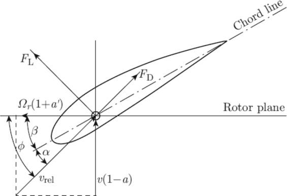
Fig. 5. Aerodynamic loads of the blade element |
Thrust, torque and power acting on the whole blade are illustrated in (2)-(4) (Hansen, 2008):
where , and are the thrust, torque and power acting of the wind turbine blade respectively. and are the lift force and drag force coefficient respectively. is the density of air, is the wind velocity, is the relative angle of wind, and are the axial and angular induction factors respectively. is the radial length of the blade sections, is the angular velocity, is the distance of the airfoil section from the blade root, is the airfoil chord length, is the number of the blade.
3.3. Hydrodynamic loads
The total hydrodynamic loads and moments on the six degrees of freedom (DOFs) of the spar platform can be split into five separate loads: a wave excitation load includes first-order linear wave excitation force and second-order wave excitation force , a radiation load , a nonlinear viscous-drag load , a hydrostatic load and a current load . The total hydrodynamic loads can be expressed by:
Specific expressions of the loads in the Eq. (5) will be given below.
The wave excitation force can be expressed as the sum of and :
The first-order linear wave excitation force can be expressed as:
where, refers to Froude-Krylov force, is radiation force.
Next, we focus on the calculation of the second-order force. Formula for calculating second-order wave force in frequency domain is shown as [26]:
where, and represent the wave amplitudes, and is the wave frequencies, and is the corresponding phases. The function and corresponds to the amplitude of the second-order force per unitary wave amplitudes and are known as the quadratic transfer functions (QTF).
The total radiation force can be determined in time domain by:
where, is the added mass coefficient at infinite frequency, is the retardation function, is the platform motion equation.
The hydrostatic load include the buoyancy force from Archimedes’ principle and the linear hydrostatic restoring force from the effects of the water-plane area and CB:
where, refers to the density of seawater, is acceleration of gravity, is the volume of water displaced when the support platform is in its undisplaced position, is the linearized hydrostatic restoring coefficient matrix, is the platform position function.
The viscous effects are not considered in numerical models using the potential theory. However, the viscous-drag load due to the viscosity of water is important to the spar platform. The slenderness ratio (L/D) of the main column, offset column and pontoon are 4.75, 3.50 and 16.9 respectively. Therefore, it is necessary to modify the wave force based on potential flow theory. The viscous-drag load is modelled by the Morison equation and expressed by:
where, L refers to the length of the cylinder, D is the diameter of the cylinder, is the viscous coefficient in the specific direction that has projection area , u is the velocity of the support platform, is the undisturbed flow velocity taken at the instantaneous position of the CG. In addition, the current load calculation can be also calculated by replacing the velocity with the velocity of the wave particle according to the Morison formula.
3.4. Mooring loads
The mooring loads are calculated in the FAST code based on finite element anchor mooring (FEAM) model [27]. The mooring line is regarded as the slender rod in the global coordinate system in the FEAM model as shown Fig. 6. The centerline of the deformed mooring line is represented by the spatial curve in Fig. 6, where represents position vector.
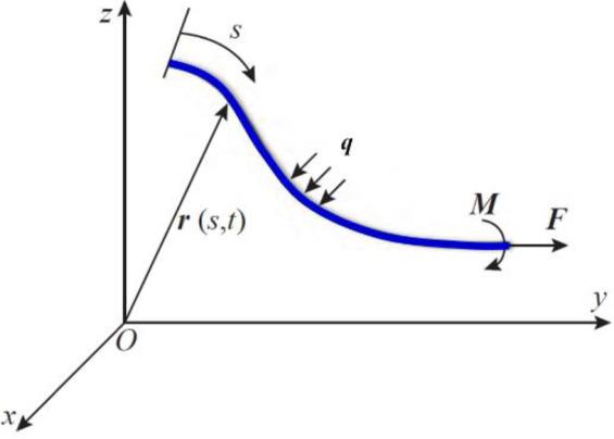
Fig. 6. Coordinate system for slender rod |
The force balance equation the unit length mooring line can be expressed by:
where, refers to the mooring force along the centerline, is the external force per unit length of mooring line, is the mass per unit length, is the rod acceleration.
The mooring force along the centerline is shown as:
where, refers to the bending stiffness, is the effective tension of mooring line, is the tension along the tangential direction, is the curvature of mooring line.
The hydrodynamic force acting on the mooring line can be expressed by the Morison equation as:
where, refers to additional mass coefficient per unit length, is Inertia coefficient per unit length, is drag coefficient per unit length, is the velocity along the normal direction, and the velocity and acceleration of the fluid in the direction normal to the centerline of the anchor chain, respectively.
The control equation of the motion of the mooring line can be obtained by substituting Eqs. (13) to (15) into Eq. (12):
where, refers to Wet weight of mooring line. Also, the mooring line needs to satisfy the tensile constraint equation:
where, is the axial stiffness of mooring line.
The control equations of the rod model are composed of Eqs. (16) and (17) together. Since the control equations are nonlinear, it is difficult to obtain analytical solutions, so the finite element method is used to solve the differential equations of motion for the elastic rod, and the above control equations can be solved by a series of algebraic equations as follows:
3.5. Numerical simulation procedure
The numerical model of multi-column low CG floating wind turbine system is constructed in the frequency domain software WADAM and the FAST code. WADAM is a frequency domain hydrodynamic calculation module of the SESAM software developed by DNV. Added mass, potential flow damping coefficient and other hydrodynamic parameters are calculated by using a 3-dimensional panel method in WADAM. To calculate the damping more accurately, the Morrison theory unit is used in the calculation model. For a floating offshore platform, second-order wave loads have a strong effect on the global responses [28], therefore it should be covered in the numerical simulation. The QTF matrixes are also calculated in the WADAM module. The platform was modeled with 5557 elements for the parts under the SWL, as shown in Fig. 7. The matrixes of surge, pitch and heave force QTFs in the low frequency range are presented in Fig. 8.
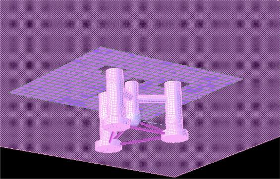
Fig. 7. Surface element meshing in WADAM |
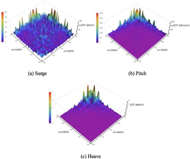
Fig. 8. Quadratic Transfer Functions (QTFs) |
Then, the files are imported into the time domain software FAST to calculate time domain responses of the multi-column low CG floating wind turbine system. The calculation process is shown in Fig. 9.
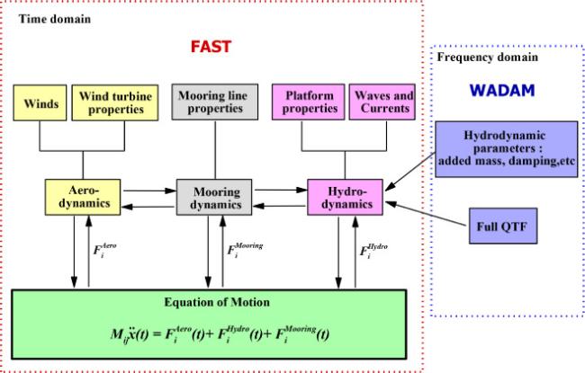
Fig. 9. Calculation structure of WADAM-FAST |
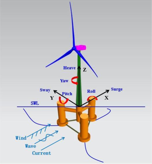
Fig. 10. Definition of coordinate system and 6 DOFs of motions for multi-column low CG FOWT |
4. Reference site and environmental conditions
The feasibility of designing a cost-effective floating support platform for FOWT is highly dependent on meeting the ocean conditions at a specific location. This paper is to investigate the feasibility of working with multi-column low CG FOWT concept in the South China Sea with relevant water depths [29]. The water depth at the site is assumed to be 50m below the still SWL. Four different sets of DLCs, accounting for operating and parked conditions, are considered here as shown in Table 6. DCL2 is the rated operating condition, and the one-year wind-wave-current conditions in the northern part of the South China Sea are selected. DLC4 is the extreme load cases with the turbine system being shut down under with 50-year environmental conditions. The wind environment is simulated by turbulent winds with Kaimal wind spectra. Wind seed of the wind turbulence is generated by the NREL TurbSim software [30]. The JONSWAP wave spectra [31] under non-typhoon conditions are applied to DLC1-DLC3. For DLC4, the JONSWAP wave spectrum model corresponding to the 50-year typhoon conditions is selected. All simulations are lasted 1 hour and 3 hours in full scale for the operational conditions and the extreme sea state, respectively.
Table 6. Design load case. |
| Design load cases | Wind (m/s) | Turbulence intensity | Wave | Current velocity (m/s) | Rotor speed (rpm) | Description | |
| Height(m) | Period(s) | ||||||
| DLC1 | 8 | 0.174 | 2.1 | 5.3 | 0.38 | 9.2 | Cut-in sea state |
| DLC2 | 10.5 | 0.154 | 4.6 | 7.7 | 0.5 | 10 | Rated sea state |
| DLC3 | 25 | 0.117 | 6.9 | 11.2 | 0.92 | 10 | Cut-out sea state |
| DLC4 | 49 | 0.104 | 8.2 | 13.8 | 1.22 | 0 | Extreme sea state |
5. Results and discussion
The prediction of coupled dynamic loads and the corresponding responses of the FOWTs is a critical part of the design process. Therefore, the coupled dynamic response results of first order and second-order obtained from numerical simulations are shown and detailed analyzed in the following section. The results are presented in both time domain and frequency domain. The time domain results are displayed as statistical values for each response parameter, including the maximum, mean and the standard deviation (STD). The statistical values presented below are the average of the statistical values based on five simulations of the same sea state to minimize the statistical uncertainty. The Fourier transform is applied to the time history response results to obtain the dynamic response spectrum. Before analyzing the results, the general coordinate system of this paper is briefly described. In this study, a right-handed Cartesian coordinate system is used with the x-axis vertical to the wind rotor plane and parallel to the wave direction. The local coordinate system of the multi-column low CG FOWT, which is considered as a rigid body with six DOFs, is defined in Fig. 10.
5.1. Natural frequency
Firstly, the natural frequency of the entire FOWT system (with mooring line) is determined by using the 6 DOFs free decay method in FAST. In the free decay test, the wind turbine stops operating and the blade pitch angle is set to 90°. The natural periods and damping coefficients obtained from the free decay simulations are presented in Table 7. It is found that, expect for heave motion, the natural periods of the multi-column low CG FOWT system remain well away from the range of wave excitation periods, thus avoiding the resonance and strong motion. Although the natural period of heave motion is relatively small, the natural period of heave motion avoids the range of periods where wave energy is concentrated.
Table 7. Decay test results. |
| DOFs | Natural period (s) | Natural frequency (rad/s) | Damping coefficient |
| Surge | 42.1 | 0.149 | 0.1193 |
| Sway | 42.1 | 0.149 | 0.1165 |
| Heave | 12.1 | 0.519 | 0.0258 |
| Roll | 30.8 | 0.203 | 0.0643 |
| Pitch | 30.8 | 0.203 | 0.0692 |
| Yaw | 17.5 | 0.358 | 0.1362 |
5.2. Response amplitude operator (RAO)
The response amplitude operator is an important parameter to describe the hydrodynamic performance of a FOWT system. White noise wave simulation is used to obtain the RAO of multi-column low CG FOWT system. White noise wave tests are performed over a range of frequencies from 0.05 to 1.2 rad/s and the wave height ranges from 0 to 10m with wave approach angle of 0°. Sway, yaw and roll motion are negligible being the heading angle of 0°, thus the related RAOs are not presented. Fig. 11 shows the RAO results for surge, pitch and heave motion of the multi-column low CG FOWT system at parked and rated wind speed operating conditions. It is found that the surge, pitch and heave RAOs are large at the nature frequency of each DOFs. The coupling effect of surge and pitch is obvious as shown in the surge and pitch RAO results. In addition, the RAO comparison results show that the RAO results at the inherent period decrease during the normal operation of the wind turbine system, which proves that the normal operation of the wind turbine is beneficial to reduce the inherent period motion responses of the FOWT. However, the 1P frequency (One time wind turbine rotation frequency) will also excite the motion responses of the FOWT while the wind turbine is operating. In addition, the effect of 1P frequency on surge and pitch motion are greater, while the effect on heave motion is minimal.

Fig. 11. RAO of the multi-column low CG FOWT system |
5.3. Platform motion
Since the incidence angle of wind, wave and current loads is 0°, for FOWTs, surge, pitch, heave and yaw are the most important motions among their six DOFS. The coupled dynamic response is the most important concern for FOWT design, thus, the coupled motion response of surge, pitch, heave and yaw motion of multi-column low CG floating wind turbine is analyzed in the following section. The comparative analysis of the effect of first-order wave forces (denoted by 1st in wave spectrum) and second-order wave forces (denoted by 2nd in wave spectrum) on the responses of the FOWT are also performed.
Fig. 12, Fig. 13, Fig. 14, Fig. 15 present the statistical characteristics and power spectral density (PSD) of surge, pitch, heave and yaw response of the multi-column low CG FOWT system, respectively. Firstly, the frequency domain responses of the multi-column FOWT system are analyzed. As observed in Figs. 12(a) and 13(a), the power spectrum density increases sharply with the increasing of wave load, and the main energy peak is shifted from the natural frequency to the wave frequency. It demonstrates that the wave frequency excitation gradually becomes the main influencing factor of the surge and pitch motion as the wave load increases. A small peak appears at the pitch frequency in the surge power spectrum, indicating that the surge and pitch motions are coupled with each other. As for the yaw power spectrum density in Fig. 15(a), the maximum energy peak of yaw occurs at the natural frequency of yaw, which indicates that responses of yaw are mainly affected by its own natural period. A small peak appears at the pitch frequency in the yaw power spectrum, which indicates that pitch motion has a certain influence on yaw motion of the multi-column FOWT system. There is no peak energy point at wave period, which indicates that when the incident angle of wave load is 0°, wave load has no influence on yaw responses.

Fig. 12. Surge responses of the multi-column low CG FOWT system |

Fig. 13. Pitch responses of the multi-column low CG FOWT system |
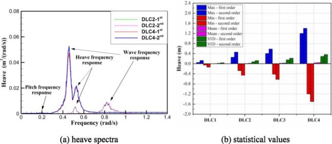
Fig. 14. Heave responses of the multi-column low CG FOWT system |

Fig. 15. Yaw responses of the multi-column low CG FOWT system |
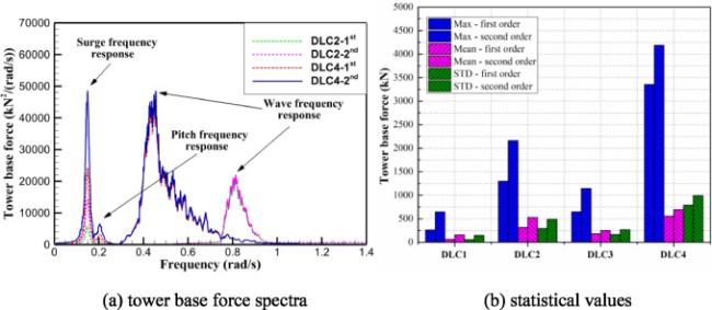
Fig. 16. Tower base force responses of the multi-column low CG FOWT system |
Another aspect of the frequency domain results shown in Figs. 12(a)–15(a) deserves attention: the results in the low frequency region of Figs. 12(a)–15(a) indicate that the second-order wave force mainly affects the low frequency resonance region and has less effect at the wave frequency. However, it can be seen from the Figs. 12(b)–15(b) of the statistical values of the response that the second-order wave force have a significant impact on the coupled responses of the multi-column FOWT system. This illustrates that second-order low frequency excitation is small compared to the wave excitation but the FOWT system is excited in resonance, so the response amplitude is comparable. It also indicates that the second-order wave forces are not negligible in the design of shallow-water FOWTs.
Finally, the time domain responses (Figs. 12(b)–15(b)) of the multi-column FOWT system are analyzed. For the rated operating sea state (DLC2), the maximum surge, pitch, heave and yaw responses are 3.73m, 2.51°, -0.458m and 0.33°. According to DNV standards DNV-OS-J103 [32], the motion responses at rated operating condition meet the normal operating requirements of wind turbine system. For the extreme sea state (DLC4), the maximum surge, pitch, heave and yaw responses are 6.96 m, 6.44°, -1.5m and 0.55°. From the statistical value, it can be seen that under the extreme sea state, the mean heave response is basically in the balance position, and the maximum heave response is less than 1% of the overall height of the multi-column FOWT, which indicates that the multi-column low CG floating foundation can effectively increase the heave damping of the FOWT and ensure safety of the FOWT under the extreme sea state. This illustrates that by adding large diameter base columns as fixed ballast tanks below the short SPAR, the multi-column deep-draft platform offers an effective function of reducing the CG and increasing the damping of heave.
5.4. Fore-aft force and moment of the tower base
For multi-column low CG FOWT system, the tower base structure is an important structure connecting the tower and floating foundation, and the tower base is far from the center of wind thrust (can be approximated as the hub), so the tower base force and bending moment is the focus of structural safety inspection during normal operation of floating wind turbine. In the following, fore-aft force and bending moment of the tower base are analyzed.
The statistical characteristics and PSD of fore-aft force and bending moment of the tower base are shown in Fig. 16, Fig. 17, respectively. As shown in Fig. 16(a), there is a coupling phenomenon between the tower base force and the surge and pitch motion, and the surge motion has the greatest influence on the force on the tower base. The same coupling phenomenon also appears in the bending moment of tower base. It can be also found that the wave excitation gradually becomes the main influencing factor of the tower base force and bending moment responses as the wave load increases. In addition, the second-order wave force has a significant effect on the low frequency motion of the tower base as shown in Figs. 16(a) and 17(a). From Fig. 17(b), it can be obtained that the maximum bending moment at the tower under extreme sea conditions is 14800 kN m, which corresponds to a maximum bending stress of 7.37Mpa. The stress results indicate that the maximum bending stress of the tower base under extreme sea conditions is still much less than the yield strength of Q345 steel, and the tower design meets the survival requirements of the multi-column low CG FOWT system under extreme operating conditions.
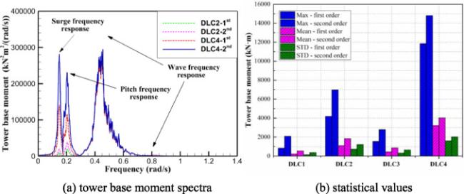
Fig. 17. |
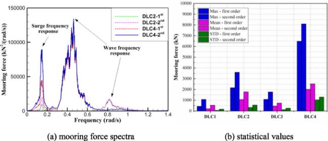
Fig. 18. Mooring force responses of the multi-column low CG FOWT system |
5.5. Mooring line tension
Finally, the mooring forces of the multi-column low CG FOWT system are studied. There are three mooring lines in the mooring system as shown in Fig. 4. The mooring line 2 and 3 are obviously more critical than line 1 by considering the direction of the incident waves. Since line 1 and 3 are symmetric, only the mooring line 1 is selected for analysis. Fig. 18 represents the response power spectrum and statistical values of the mooring force. As shown in Fig. 18(a), the mooring force and surge motion are strongly coupled and the second-order wave force has a significant effect on mooring system. However, as the environmental load increases, the influence of wave excitation on the mooring system gradually increases, while the proportion of the effect of low frequency response gradually decreases. From the statistical value, it can be known that the maximum force on mooring line is 8100kN, including the initial pre-tension. This value gives a safety factor of 2.0. It is indicated that the mooring system has a sufficient safety factor.
6. Conclusions
A new concept of multi-column low CG floating wind turbine platform for shallow waters in the South China Sea was designed and validated. The numerical simulation is constructed by the time domain software FAST and the frequency domain software WADAM. The simulation model is constructed with second-order wave loads and the results are compared and analyzed. The dynamic behaviors of multi-column low CG FOWT system under normal operation and parked conditions are presented. The influence of second-order wave forces on the motion response of the multi-column platform, fore-aft force and moment of the tower base and mooring force are researched respectively.
Based on the white noise wave simulation, it is observed that the surge and pitch motions are strongly coupled. In addition, from the frequency domain results, it is found that the tower base dynamic response and mooring force are coupled with the surge and pitch motion. Besides, with the increase of environmental loads, wave frequency responses gradually become the main influencing factor of coupled dynamic responses of FOWTs.
From the analysis of the statistical results, it can be seen that the average heave response is basically in the balance position, and the maximum heave response is less than 1% of the overall height of the multi-column low CG FOWT, which indicates that by adding large diameter base columns as fixed ballast tanks below the short SPAR, the multi-column deep-draft platform offers an effective function of reducing the CG and increasing the damping of heave.
More importantly, the frequency domain results shown in the low frequency region indicate that the second-order wave force mainly affects the low frequency resonance responses and has less effect at the wave responses. The main reason is that the second-order slow drift force has a great influence on the low frequency motion and the installed location of the multi-column low CG FOWT is at shallow water area.
Last but not least, it is observed from longitudinal comparative analysis of the motion response spectra that the proportion of the second-order response decrease with the increasing severity of the wave load. Thus, in the subsequent design of shallow water FOWT system, we should pay more attention to the influence of second-order response at operational condition.
According to IEC-61400-3 [33] requirements, the dynamic responses at rated operating condition and extreme condition meet the normal operating requirements and extreme survival requirements of FOWT system in the shallow water (50m) of South China Sea. The results presented herein characterize the coupled dynamic response of a multi-column low CG FOWT system located in shallow water area. And it will help inform relevant modifications to the initial design of the shallow water FOWT. Future work will focus on the structural optimization of the multi-column low CG FOWT system and model test in a wave tank.
Declaration of Competing Interest
The authors declare that they have no known competing financial interests or personal relationships that could have appeared to influence the work reported in this paper.
