
Highlight
• Self-powered biomonitoring textiles via biomechanical, body heat, and biochemical energy conversion are discussed.
• Platform technologies, including PENG, TENG, MEG, TEG and BFC are systematically introduced.
• Self-powered biomonitoring textiles pave a compelling road to personalized healthcare
Introduction
The current centralized healthcare system suffers from inefficiencies and deficiencies in providing medical servies. Traditional medical devices face challenges including their cumbersome size, lack of wearability, reliance on a power supply, among others, making it difficult to provide timely and personalized healthcare services in the era of the Internet of things [1⇓⇓-4]. Continuous monitoring of physiological state is critical to realize early diagnostics and timely prevention, which could enable a transition from the current reactive & disease-centric healthcare system to a personalized model with a focus on disease prevention & health promotion [5⇓-7]. Wearable bioelectronics in the skin-interfacing format can provide continuous vital signs monitoring [8⇓⇓-11]. However, the wide spread adoption of wearable bioelectronics for healthcare is largely shadowed by device rigidity, poor breathability, and wearing discomfort [12,13].
Textiles, which have been a part of human civilization for thousands of years, are made from both natural materials such as silk and cotton, and synthetic materials such as polyamide and polyester. These materials can be made into textile bioelectronic devices via scalable weaving, knitting, braid, printing, and electrospinning, showing great wearing comfort and breathability [14⇓⇓⇓⇓-19]. Conventional fiber fabrication techniques include coating [20,21], spinning [22,23], and thermal drawing [24⇓-26]. These various types of fibers can also be arranged into different architectures and structures in textiles [8,27], endowing them with excellent flexibility, breathability, abrasion resistance, and material integration. An increasing number of platform technologies, including electroluminescent [28], piezoresistive [29], thermoelectric [30,31], and photovoltaic [32,33] platforms have been utilized to develop smart healthcare textiles [34⇓-36]. Among them, self-powered biomonitoring textiles that rely on piezoelectric [25,37], triboelectric [38⇓-40], magnetoelastic [41,42], and electrochemical [43,44] approaches offer unique and compelling features that have attracted significant attention. Self-powered textiles have the capability of sustainably converting the renewable energy from the human body such as biomechanical, body heat, and biochemical energy into electrical signals for healthcare purposes. They not only weaken the dependance of wearable bioelectronics on power supply, but they also provide highly sensitive and real-time information to monitor human physiological states. Additionally, selfpowered textiles are also environmentally friendly, simple to manufacture, inexpensive, which can be effectively integrated into daily wear such as clothing, masks, wristbands, and other garments for continuous monitoring.
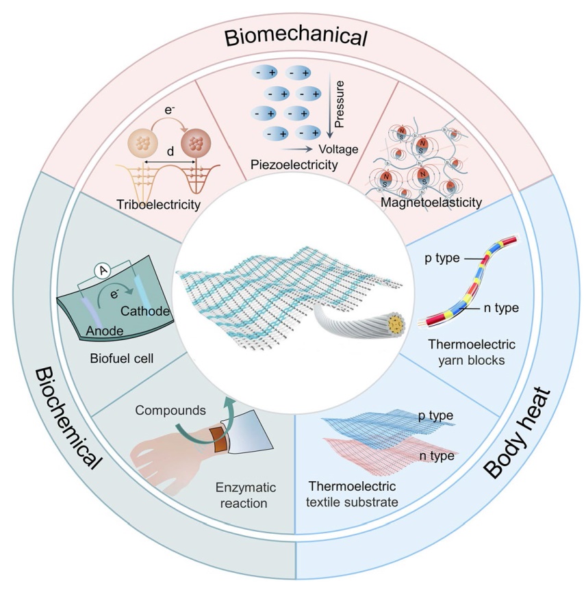
In this review, we will comprehensively review various self-powered biomonitoring textiles. We will begin by briefly discussing the physiological signals that can be monitored. Then, we will present the progress of self-powered biomonitoring textiles which utilize the on-body renewable energy sources: biomechanical, body heat, and biochemical energy (Fig. 1). We will illustrate the mechanisms of each of these self-powered textiles and describe how they can monitor various physiological parameters. Finally, we will discuss the challenges within the community of self-powered biomonitoring textiles. This review provides a critical analysis of the current advances in smart biomonitoring textiles and the insights into remaining challenges and future directions.

Fig. 1 Platform technologies for self-powered biomonitoring textiles. For self-powered biomechanical sensing, we have systematically introduced PENGs, TENGs and MEGs. The TEGs and BFCs are introduced for self-powered boy temperature and biochemical sensing, respectively. This review provides a critical analysis of the current advances in smart textiles working in the self-powered manner and the insights into remaining challenges and future directions, paving a compelling road to personalized healthcare |
Self-powered biomechanical activities monitoring
Large-to-small-amplitude biomechanical motions are abundant around the human body, ranging from large-scale motions like knee movements [45], sleep signals [46], and voice direction and communication [25], to almost invisible motions like cardiovascular movements [47⇓-49] and respiratory systems [41]. Typical working mechanisms for biomechanical energy conversion relies on the piezoelectric effect [37,50], triboelectric effect [51], and the recently discovered magnetoelastic effect in soft matter systems [42,52]. These wearable self-powered sensors can collect energy from biomechanical motions around the human body to realize continuous biomonitoring. The self-powered mechanism has achieved widespread attention given their potential for personalized healthcare with lower power consumption. Textiles are ubiquitous in our daily life due to their excellent biocompatibility, wearing comfort, and softness, making them a compelling platform for wearable biomonitoring devices.
Piezoelectric effect
Piezoelectricity is defined as a change in electric polarization due to a change in applied stress [37,50,53,54]. A piezoelectric nanogenerator (PENG) is composed of a piezoelectric material layer sandwiched between an upper and a lower electrode layer, which is a type of technology that converts mechanical motions by using small-scale physical change induced polarization [54]. With the applied mechanical force, the piezoelectric material layer can change the dipole moment of the dipole to produce an accumulation of charges on the electrodes, thereby obtaining the generated inner electrical potential difference [54⇓⇓⇓⇓⇓⇓-61]. Therefore, the PENGs can effectively convert mechanical motions into electrical signals without any additional power supply [62]. These electrical signals contain rich information regarding the mechanical motion of the body, thus we can develop the PENGs into active sensors, namely, the piezoelectric sensors, which have received widespread attention due to their mechanical flexibility, long lifespans, and chemical stability [63]. Among all PENG-based sensors, textile-based forms are particularly attractive because of their lightweight, durable, flexible, and wearable comfort characteristics. At present, a large number of spinning and weaving techniques are used to prepare flexible self-powered piezoelectric textiles, which have been widely used for motion, sound, and cardiovascular monitoring.
Recently, Mokhtari et al. reported a wearable electronic textile using nanostructured hybrid piezoelectric fibers [45]. The self-powered fibers used conductive fibers as electrodes and were assembled with poly(vinylidene fluoride)/barium titanate nanoparticles (PVDF/BTO) piezoelectric energy harvesting fibers, which were then built into woven, braided, and knitted into energy generators. The output power density of the woven wearable energy generator is about 300% higher than that of the previous design, and the knitted technology makes the textile structure durable and tough (Fig. 2a). The self-powered textile can be integrated into clothing to collect and store energy, and transmit its voltage output data as well as information about the tension it is experiencing. This capability can help determine the manner in which a motion is made (Fig. 2b), as well as the bending angle of the knee joint and other tasks related to proprioception (Fig. 2c).

Fig. 2 Self-powered biomechanical monitoring textiles based on piezoelectric effect. a Wearable PVDF/BTO piezoelectric sensing textile based on circular knitted fiber energy generators, which make the textile more durable and tough (scale bar, 5 mm). b The waveform of the voltage generated by bending the woven textile at the knee joint during walking and running. c The voltages generated when the knee joint was flexed to 0, 45, and 90 degrees [45]. Copyright (2020) WILEY-VCH Verlag GmbH & Co. d Schematic illustration of muscle fiber inspired piezoelectric (MFP) bilaterally laminated assembled textiles for biomedical monitoring. Sensing performance of MFP textiles: e single-shot static and dynamic pulse wave motion analysis and f dynamic output voltage curves when different words like "Hi", "OK", and "sensor" are spoken [64]. Copyright (2021) WILEY-VCH Verlag GmbH & Co. g The acoustic textile of high-modulus Twaron yarns and cotton yarns arranged at right angles and woven with single-strand piezoelectric elastic fiber transducers. h The chest textile can monitor heart sounds, providing heart rate and the S1 and S2 components of heart sounds. i Two pieces of textiles can act as microphones and speakers for acoustic communication [25]. Copyright (2020) Springer Nature |
In addition, self-powered PENG fabrics also have the potential to monitor gentle pulse vibration. Su et al. developed a nonwoven self-powered piezoelectric textile inspired by muscle fibers [64]. To achieve this, they combined polydopamine-modified PVDF/BTO composite electrospun nanofibers (PDA@BTO/PVDF) with aluminum foil electrodes and the PET substrate before bilaterally laminating all the components together (Fig. 2d). This textile has great potential for portable medical diagnostics. For example, it can be placed on the radial artery of the wrist to dynamically monitor subtle changes in arterial blood pressure and generate typical pulse waveform peaks (P0-P3) under both static and excised conditions (Fig. 2e). The textile sensor can also be worn against the neck to monitor throat vibrations to perform speech recognition (Fig. 2f). To conclude, this work presents an innovative approach to optimizing self-powered medical monitoring sensors.
In order to further study electronic textiles capable of monitoring weak auditory signals, Yan et al. developed a biomimetic eardrum made from a piezoelectric fiber-woven textile inspired by the human auditory system [25]. The piezoelectric elastomeric fiber was braided into a textile with perpendicular high-modulus Twaron yarns and cotton yarns as fiber transducers providing electrical output (Fig. 2g). Because the textile can detect weak sound signals as low as 10- 7 atm, it can be worn on the chest to monitor heart rate and heart sounds (S1 and S2) (Fig. 2h). The acoustic textile can also be woven into two different shirts to function as a speaker to emit and a microphone to receive the speech, enabling bidirectional acoustic communication between the two shirts (Fig. 2i). Additionally, the textile can continuously monitor the wearer’s heart and breathing conditions in a real-time and over a long period. These implementations address current problems with textile sensing, such as large fiber transducer area, low sensitivity, and low detection limit, providing great promise for future textile-based wearable biomedical sensors.
Triboelectric effect
Due to the complex fabrication process and limited material selection, piezoelectric sensors are restricted in certain aspects. Therefore, other potential energy conversion mechanisms are sought after to develop self-powered sensors. The triboelectric nanogenerators (TENG) has attracted much attention since 2012 [51]. Based on the coupling of the triboelectric effect and electrostatic induction between dissimilar materials, TENG can convert mechanical motions into electrical signals [65⇓⇓⇓-69]. At the same time, it is also lightweight, flexible, low-cost, etc. [10,11,65,66,70⇓-72]. These features and self-powered properties make TENGs widely used in various wearable and implantable healthcarerelated applications, such as biomonitoring [73⇓⇓⇓⇓⇓-79], therapy [80⇓⇓⇓⇓⇓-86], and energy harvesting [87⇓-89]. Among them, TENG-based wearable biomonitoring textiles can rely on economically available materials and scalable manufacturing techniques to provide a comfortable and non-invasive way to provide real-time physiological monitoring, which is expected to be widely used in home and clinical healthcare systems in the future [90].
One of the popular biomonitoring applications is for sleep quality evaluation. Sleep is a mechanism by which humans rest and recover. However, a significant number of individuals currently encounter various sleep disorders such as insomnia, sleep apnea, and even circadian rhythm disorders. In addition, potentially sudden or unexpected manifestations of diseases during sleep, such as myocardial infarction, hypertension, etc., will bring great harm to human physical and mental health [91,92]. Therefore, monitoring sleep quality, posture, and vital signs during sleep is particularly important. Currently, commonly used monitoring techniques in clinical practice, such as dynamic electrocardiogram, blood oxygen saturation detecting system are limited due to their complexity and lack of privacy. TENG is a practical way to prepare large-scale self-powered sleep monitoring textiles, which can non-invasively, comfortably, and efficiently monitor the physiological indicators of human sleep in real-time. Lin et al. developed a TENGbased sandwich structure sensor array with wavy PET as an intermediate layer to evaluate sleep behavior and quality in real-time [46]. Once the external force causes the contact area between the PET layer and the two upper and lower conductive fiber layers to change, a potential difference will be established between them, which will drive electrons to flow from the conductive fiber to the ground and generate electrical signals. Thus, the textile can be self-powered to warn the users of the risk of falling out of bed during sleep, which is helpful for clinical applications. However, the thickness of PET layer can interfere with the comfort of the overall sleep experience, and the textile cannot monitor sleep posture and physiological indicators simultaneously. To address this, Zhou et al. proposed an ultra-soft textile woven from a functional fiber with a skin-core structure (Fig. 3a) [93]. The fiber consists of a twisted conductive yarn as the core and an ultra-thin silicone outer skin. The textile can simultaneously monitor sleep posture, respiration, and act as a ballistocardiograph (BCG), improving sleep quality and reducing the risk of death during sleep.

Fig. 3 Self-powered biomechanical monitoring textiles based on triboelectric effect. a Photograph of the single-layered ultra-softsmart textile (scale bar, 10 cm) [93]. Copyright (2020) Elsevier. (b) Schematic illustration of textile-based sensor and (c) OSAHS patient pulse measurement wave signal [47]. Copyright (2020) Elsevier. d Schematic of triboelectric textile sensor and e schematic for cardiovascular atherosclerosis progression process (I-VI). f ISC performance of the textile friction sensor under stationary, moving, and wet conditions [48]. Copyright (2021) WILEY-VCH Verlag GmbH & Co. g Design of a triboelectric textile sensor network mask for respiration monitoring. h Schematic diagram of the mask sensor network model and pressure distribution inside the mask. i Phase shift and voltage curves of five channels in the sensor network [94]. Copyright (2022) WILEY-VCH Verlag GmbH & Co |
The arterial pulse wave is one of the most representative biomedical signals, as it contains physiological and pathological information about the human cardiovascular system. However, there are a series of healthcare challenges in pulse detection. For example, the pulse signal transmitted on the surface of the artery is very faint. Additionally, the sensor of the charging mechanism on the surface can easily interfere with biomedical signal monitoring. Finally, it can be uncomfortable to wear due to poor air permeability. TENG-based self-powered textiles have great potential in pulse monitoring, as their self-powered properties allow for high sensitivity with less signal interference, and the textile’s excellent breathability ensures user comfort. Fan et al. developed a full cardigan knitted triboelectric all-textile sensor array (TATSA) that can be stitched to the cuff of clothing to monitor pulse signals, demonstrating high-pressure sensitivity (7.84 mV Pa− 1) and fast response time (20 ms) [38]. At the same time, Meng et al. used a different weaving and manufacturing strategy to fabricate a double-layer flower-shaped textile sensor (Fig. 3b). They mixed polyester-metal hybrid fiber upper layer forming the flower shape, and lower layer silver-coated polyester fabric as the base, which can convert the pulse pressure into electrical signals [47]. The textile, used as a triboelectric layer and electrode, has a sensitivity of can 3.88 mV Pa− 1, sufficient to accurately acquire physiological signals from elderly patients for indicating obstructive respiratory events (Fig. 3c). In order to exclude external environmental disturbances and monitor pulse signals more accurately, Fang et al. proposed a machine learning-assisted textile triboelectric sensor [48], the structure of which is shown in Fig. 3d, with an outer textile layer can that blocks out external airflow noise and is waterproof. Nonwoven fluorinated ethylene propylene (FEP) and hierarchically structured carbon nanotubes (CNT) serve as triboelectric layers, with a poly(dimethylsiloxane) (PDMS) inner encapsulation layer for biocompatibility. This textile triboelectric sensor can obtain high-fidelity pulse waveforms and all pulse wave characteristics even under moving and wet conditions (Fig. 3f). Furthermore, according to the waveform analysis, it can obtain physiological indicators such as blood pressure, vascular status, and wall stiffness, enabling the prevention of potential vascular disorders such as atherosclerosis (Fig. 3e).
In addition to arterial pulse testing, machine learningassisted triboelectric textile sensors can also be used for respiratory monitoring and diagnostics. Recently, Fang et al. reported a self-powered textile triboelectric sensor network for face masks made out of twisted triboelectric PVDF yarns and epoxy resin [94]. The textile is permeable, moisture-proof, and highly sensitive (0.46 mV Pa− 1) with a short response time (0.28 s). The sensor network consists of five channels (Fig. 3i) and uses a deep learning algorithm based on a one-dimensional convolutional neural network (CNN) is used to identify a breathing pattern (Fig. 3h). The system is capable of real-time monitoring and is adaptive in the process of diagnosing underlying respiratory diseases.
Magnetoelastic effect
The magnetoelastic effect, also named as the Villari effect, was discovered in 1865 by Italian experimental physicist Emilio Villari, refers to the variation of the magnetic field of a material under mechanical stress [95,96]. This effect is typically observed in rigid metal and metal alloys in the past 156 years when an external magnetic field is applied. The magnetoelastic effect has been ignored in the field of soft bioelectronics for the following several reasons: the magnetization variation in the biomechanical stress range is limited; the requirement of the external magnetic field induces complex and bulky structure, and there exists a gigantic mismatch of mechanical modulus (six orders of magnitude difference) between rigid metal/metal alloy and soft biosystems (i.e., human tissue). In 2021, the research group at the University of California, Los Angeles lead by Prof. Jun Chen discovered the giant magnetoelastic effect in a soft polymer system and use it to construct a soft magnetoelastic generator (MEG), which paves a fundamentally new way to build up intrinsically waterproof and biocompatible self-powered bioelectronics for human-body-centered energy, sensing, and therapeutic applications [41,42,52,97⇓⇓⇓⇓-102].
MEGs have received extensive attention as novel selfpowered sensors, which can convert biomechanical activities into high-fidelity and analyzable electrical signals through a two-step conversion mechanism, namely, the coupling effect of magnetoelastic effect and electromagnetic induction [41,42,52,97⇓⇓⇓⇓-102]. Specifically, the magnetomechanical coupling (MC) layer dispersed with micro-/nano-magnets can be deformed under the biomechanical motions. The micro-/nano-magnets can rotate or move in the system, resulting in the magnetic flux changes which can be harnessed to generate currents in the magnetic induction (MI) layer. Compared with PENGs and TENGs, the loss of magnetic field strength through water is negligible, which makes the MEGs intrinscially waterproof. Thus, it can be used in sweaty, humid, and/or fluid environments without the needs of encapsulation layers. The MEGs can offer high short-circuit current density and low internal impedance, providing an ideal platform technology for self-powered biomonitoring [41]. For instance, MEG-based self-powered biomonitoring textiles for respiratory monitoring and cardiovascular monitoring have been reported to the community [41,42]. One textile MEG consists of a soft magnetoelastic membrane, a conductive coil, and a textile substrate (Fig. 4a) [41]. Textile MEGs can be seamlessly sewn onto clothing to precisely record various breathing patterns during normal breathing, rapid breathing, and coughing (Fig. 4b). With the assistance of machine learning algorithm, a respiratory monitoring system based on the textile MEG was developed (Fig. 4c). This system can amplify, filter, collect and process the electrical signals to obtain biomedical information on respiratory patterns, intensity, frequency, and time. Moreover, the data can then be transmitted to a mobile cellphone application (APP) as an interface for interaction with the patient. Another textile MEG is made of magnetic fibers interlaced with conductive yarns (Fig. 4d) [42]. The conductive yarns are composed of silver-plated nylon fibers and nylon fibers wounded by a braiding machine. Wristband-textured MEGs under tiny arterial pressure fluctuations (Fig. 4f) can be converted into high-quality electric signals for further cardiovascular characterization. As shown in Figs. 4e and g, a clear pulse signal can be continuously measured even when the textile MEG worn in the underwater situation. Ultimately, textile MEG wristbands equipped with built-in algorithms and customized APPs was able to upload health data to the cloud, allowing doctors to easily access them through authorization, providing a comprehensive solution for personalized medicine and cardiovascular management.

Fig. 4 Self-powered biomechanical monitoring textiles based on magnetoelastic effect. a Textile MEG assembled from conductive yarn, soft magnetoelastic film, and textile substrate. b MEG textile monitoring three different breathing patterns: normal breathing, rapid breathing, and coughing. c Photographs of MEG textile and custom APP [41]. Copyright (2021) Elsevier. d Schematic diagram of the interlacing MEG textile. e Photograph of a textile wristband used as a pulse sensor (scale bar, 2 cm). f Schematic illustration of the working principle of the pulse monitoring MEG textile. g Waveforms of the pulse monitoring wristband in sweat and water for one heartbeat cycle, the shaded area identifies the standard deviation of the five waveform results. h Building a personalized healthcare database: uploading data to cloud for data-driven diagnosis [42]. Copyright (2021) Springer Nature |
Self-powered body temperature monitoring
The temperature of the human body is one of the key indicators of the health status. Body heat is capable of selfregulating to maintain a body temperature within a range of 36 °C to 37 °C, and its changes provide physiological information related to cardiovascular health, cognitive status, wound healing, and many other conditions [103]. Traditional methods rely on devices such as thermometers, whose rigidity and weight are not suitable for providing continuous body temperature monitoring. Wearable bioelectronics designed for continuous body heat monitoring can exhibit high sensitivity, fast response, and good biocompatibility, thus attracting extensive attention [104,105].
With the deepening research on thermoelectric materials [106,107], the combination of these materials with thermoelectric properties and textiles has currently become a research hotspot. Currently, there are two working mechanisms that can be used to monitor heat from the body, one is the pyroelectric effect driven by the temperature difference over time [108⇓⇓-111]. However, since the temperature of the human body surface generally remains stable at around 33.5 ℃ and does not change much over time, its efficiency of collecting heat energy is low [112]. The other mechanism is based on the thermoelectric effect generated by the temperature difference between the human body and the surrounding environment. This temperature difference can continuously generate a heat flow exceeding 10 mW cm-2 [113], which can be used to drive the thermoelectric generators (TEGs) attached to the human skin. The working principle is that the charge carriers inside the thermoelectric material diffuse from the hot side (skin) to the cold side (environment) under the action of the temperature gradient in space to generate electricity [106,113].
Herein, we summarize from the perspective of two methods for manufacturing heat monitoring textiles for the human body. One is based on existing textile substrates for use in clothing, such as silk, polyester, glass fabric, and so on [114⇓⇓-117]. Materials with thermoelectric properties are attached by fabrication methods like dispenser printing. Another way is to manufacture functional yarns first and then forming them into textiles with thermoelectric effects by means of wrapping, weaving, and knitting methods [30,31]. These active thermoelectric textile-based generators not only provide various architectures for sensing, energy harvesting, and thermal management but also set the stage for a wide implementation of multifunctional electronics.
Textile substrate
Wearable TEG based textile substrates have been demonstrated as a feasible and low-cost strategy to fabricate thermoelectric devices. In the form of clothing, the thermoelectric materials can be delivered into the interspace of the textiles. These devices offer extensive coverage for thermal energy harvesting across the surface area of the human body, ensuring comfortable mobility for the wearer.
Currently, most researchers fabricate textile substrate TEG through dispenser printing techniques, which is commonly used in preparing functional surfaces for high heat resistive, thin, and flexible substrates [118,119]. As shown in Fig. 5a, Kim et al. reported the concept of embedding thermoelectric p-type (Sb2Te3) and n-type (Bi2Te3) materials into a polymer textile substrate by printing [114]. A series of new technical breakthroughs were integrated due to the high thermal tolerance of the glass textile (600 ℃), realizing a textile-based TEG with thin (50 μm), lightweight (0.13 g cm−2), and flexible achievements. The output volatility of the TEG is positively correlated with the temperature difference between its two ends, thus indirectly realizing the monitoring of the human body’s temperature.

Fig. 5 Self-powered body temperature monitoring textiles based on thermoelectric effect. a Schematic illustration of the screen-printed Bi2Te3 and Sb2Te3 films on glass textile. Reproduced from [114] with permission of the Royal Society of Chemistry. b Temperature-sensing mechanism of thermoelectric textile. c Temperature response resolution of thermoelectric textile within 0.1 K [120]. Copyright (2020) American Chemical Society d Schematic of the continuously alternating extrusion process. e The flexible continuous TEG composed of alternating p/n-type fiber made from SWCNT. f TEG textile structure and its thermal energy harvesting schematic illustration in an out-of-plane direction. g Energy harvesting of a TEG textile attached to the arm at various states [30]. Copyright (2020) Springer Nature h Schematic illustration of prepared TE fibers, TE fibers wrapped with acrylic fibers, and TE loops. i The output voltage contrast of the two TEGs at various steady temperature differences given by Peltier elements [31]. Copyright (2020) Springer Nature |
In 2016, a simple and easy way to conduct the process of dispenser printing was proposed by Siddique et al. to fabricate the polyester textile-based TEG [117]. The complete process was performed manually (except the curing step), and the prototype can be used as an alternative power source for self-powered portable electronic devices. Organic thermoelectric material poly(3,4-ethylenedioxythiophene) poly(styrenesulfonate) (PEDOT:PSS) was introduced into the development of the large-area self-powered temperature monitoring textile by Li et al. [120] (Fig. 5b). The voltage generated by the textile rises as the temperature difference between the body and the environment increases. As shown in Fig. 5c, a small change in ΔT will lead to a significant change in the generated voltage, and the temperature sensing resolution is as low as 0.1 K, indicating that the textile has accurate temperature sensing capability. In addition, the key parameters of temperature sensing such as resolution, stability, and response time (1 s) are excellent.
Yarns as building blocks
Although the vast majority of TEG-based textiles are manufactured using the coating process on the basis of existing regular textiles, the space efficiency and mechanical friction induced by body movement still need improvement, which may result in the unstable thermoelectric performance of the textile-based TEG. To solve these potential problems, researchers have proposed lots of solutions involving fiber and yarn dimensions [30,31,121]. The coating technique was introduced into the dimension of the fiber by Lee et al. [121]. In this study, on the basis of electrospinning PAN nanofiber sheets, the stencil-mask-based method was used to deposit p-Au-n segments, then twisted to convert them into tiger yarns. Then tiger yarns can be woven with insulating yarns to form the tiger-yarn textile structure. This structure provides textile thickness direction thermal gradient, suitable for through-thickness thermoelectric power generation. An outstanding power output of up to 8.6 W m−2 is obtained with a 200 ℃ temperature difference.
In order to produce p/n-type thermoelectric segment fibers with high homogeneity and good interface bonding, Ding et al. applied the colloidal gelation extrusion into making axially aligned thermal fibers (Fig. 5d) [30]. The alternating p/n-type fiber consisting of single-walled carbon nanotubes (SWCNTs) and polyvinyl alcohol (PVA) hydrocolloids can provide convenience for further integration into textile electronics (Fig. 5e). Then the segmented fibers were plain weaved into flexible textile, and the p/n-type units were connected in series (Fig. 5f). To embody body heat monitoring, the TEG textile is worn on the monitor’s arm. The local body surface temperatures under different states, such as sleep, work, and exercise, produce different thermoelectric voltages of 5, 7, and 12 mV, respectively (Fig. 5g).
Taking different approaches to break the invalid easy coating textile limit, Sun et al. used alternatively doped carbon nanotube fibers incorporated with acrylic fibers to weave into π-type thermoelectric textiles (Fig. 5h) [31]. The textile TEG shows thermal resistance matching, outstanding stretchability, and slight power degradation. The unique doping method and logical structure of the textile lead to a high thermoelectric performance with a peak power density of 70 mW m−2 at a temperature difference of 44 K. It also produced a stable output in various steady temperature differences, demonstrating a promising approach toward scalable thermoelectric textile fabrication (Fig. 5i).
Self-powered biochemical monitoring
In addition to biomechanical energy and body heat, our bodies also contain various bodily fluids with biochemical energy, such as blood, saliva and urine. A variety of biofuels like glucose and lactate are contained in these fluids. They are not only capable of reflecting the level of biomarkers but also containing biochemical energy, which could be harnessed to generate electricity through the bioelectrocatalytic process to sense the metabolites [122,123]. The technology holds great promise for self-powered monitoring of various biomarkers to indicate personal health.
Biofuel cells (BFCs), which are capable of continuously harvesting energy from bioelectrocatalytic reactions of human metabolites [124⇓⇓⇓⇓-129], have been widely demonstrated for self-powered biomedical applications such as microneedles [122], implantable batteries [130], microfluidic systems [131], electronic skins [132], etc. Based on the double coiling process of soft carbon nanotube (CNT) materials and guest materials [133], Kwon et al. stacked and twisted CNT materials with excellent electrical conductivity to prepare yarn electrodes (Fig. 6a) [43]. The fabricated yarn electrodes can be helically wound on glass rods or woven into textiles, showing good mechanical strength and flexibility (Fig. 6b). The prepared glucose BFC provided a maximum output of 2.18 mW cm−2 and an open-circuit voltage (Voc) of 0.70 V, which is encouraging for textile BFC platform to self-powered biomonitoring and energy harvesting applications.

Fig. 6 Self-powered biochemical monitoring textiles based on the biofuel cells (BFCs). a Schematic illustration of the structure and function of the BFC anode and cathode yarns, indicating the associated electron transfer processes and chemical transformations. b Photograph of woven textile BFC (scale bar, 500 μm) [43]. Copyright (2014) Springer Nature. c Stretchable self-powered textile-based sensor for the enzymatic reaction of lactate. d Mechanical resilience test with before (left) and during (right) multiplex deformations. e Voltage output values obtained from self-powered textiles. f The real-time biological signals monitored by the sock-based self-powered BFC sensor can be wirelessly read and recorded using a smartphone. Reproduced from [134] with permission of The Royal Society of Chemistry. g System diagram of the wearable energy microgrid, which consists of TENG, BFC, SC module, and ECD system. h Microgrid performance during actual motion. Power the ECD sensor during a 10-min workout followed by a 20-min rest. The voltage-time curves of the energy microgrid system when only BFC or TENG and both operate together are analyzed separately [125]. Copyright (2020) Springer Nature |
In order to achieve a higher degree of integration of BFCs and smart textiles. Prof. Joseph Wang’s team from the University of California, San Diego, has proposed textile-based stretchable enzyme BFCs as self-powered sensors for the first time with stable output power after over 100 cycles of stretching at 100% [134]. In the BFC, LOx and Ag2O were used as the bioanode and cathode, respectively (Fig. 6c). The biofuel was enzymatically oxidized on the anode to release electrons, and the silver oxide at the cathode accepted electrons to realize the power path. The self-powered BFC array was manufactured by screen printing technology on stretchable textile, and it displays outstanding mechanical resilience with multiplex deformations like twisting (Fig. 6d). As a result, the sensor can obtain a self-generated voltage output from lactic acid (Fig. 6e), and when the sensor device is printed inside a sock, a smartphone can be used to read and record the real-time signal generated by the self-powered biosensor (Fig. 6f).
In addition to biochemical sensing based on the BFC self-powered mechanism, biochemical energy harvesting driven by BFC has also received extensive attention. In later work, the same group produced the first demonstration of a wearable biochemical self-powered energy system, a textilebased supercapacitor (SC)-BFC hybrid system developed through screen printing stretchable inks technique [44]. The first coated styrene ethylene butylene styrene (SEBS) layer is used to smoothen the textile surface, and then print SC ink as well as polyurethane (PU) layer is used to enhance the inter-layer adhesion. The hybrid textile system can be fabricated at high throughput and at low cost. This successful integration facilitates the development of self-sustaining body energy and represents an important step toward selfpowered wearable textiles for healthcare, energy harvesting, and biomonitoring applications.
Generally, compared with MEGs, TENGs have much higher voltage output but lower current because of the triboelectric effect and high inner impedance. Different from the mechanical energy harvesting devices, which tend to output random and alternative power, the BFC can provide a relatively stable power supply because of the electrochemical reaction from body fluid. In addition, TENGs, PENGs, MEGs, and BFCs can work simultaneously and convert various energy forms from the human body or its surrounding into electrical energy. Thus, cooperative self-powered electronics applications can be developed based on the integration of various modules that can compensate for each other. Recently, the team of Prof. Joseph Wang proposed the concept of an electronic textile microgrid system using BFC and TENG, to be integrated into a shirt, and attached to the arms, torso, and chest to harvest energy from both biomechanical motion and sweat metabolites (Fig. 6g) [125]. The combination of the two types of self-powered textiles makes up for the delay in perspiration as well as the limitation of TENG when there is a lack of movement, and the biomonitoring function can boot quickly within 3 min to generate the power (Fig. 6h). The microgrid can store and regulate the harvested energy through efficient paired SC modules to efficiently power wearable applications such as Na+ potential sensor-electrochromic display (ECD) systems for biochemical monitoring driven by self-powered energy harvesting systems. The concept of a wearable microgrid and its design principles are expected to facilitate systemlevel considerations for the integration of various novel modules into next generation self-powered and autonomous biomonitoring systems.
Energy harvesting textiles as power supply
As biomonitoring devices, textiles can be employed as energy harvesting devices performing the role of a sustainable power supply for bioelectronic devices realizing selfpowered biomonitoring [8,21]. Featured with flexibility, shape adaptability, and wearing comfort, the energy-harvesting textiles can sustainably drive energy-consuming electronic devices to achieve biomonitoring potentials [135].
Biomechanical energy harvesting can collect various energy forms from the motion of human body via textilebased generators, providing a renewable, convenient, and cost-effective energy resource for body electronics networks [136⇓-138]. An energy harvesting textile was developed by combining traditional and triboelectric fibers together, working as a power supply with enhanced power output and vibrational energy harvesting ability [139]. Here, the researchers used a multiaxial winding method for improving the yarn’s electrical conductivity and mechanical robustness. In this method, a single yarn travels axially in a helical path and interweaves with other yarns across the entire cross-section. Then, the team fabricated a 3D braided TENG (3DB-TENG) through a four-step rectangular weaving technique on a 3D weaving machine. The electricity generated by the textile can be stored and continuously powered for wearable electronic monitoring devices, such as temperature and humidity meters as well as electronic meters. The corresponding charging voltage shows that the device starts to operate once the threshold voltage is reached and can continue to operate under continuous charging. Therefore, the developed 3DB-TENG has the potential to be used as a wearable power source in the future.
Meanwhile, the piezoelectric effect has facilitated the development of flexible wearable devices and energy harvesting devices over the past few years [140,141]. However, due to the mismatch of strength and dielectric constant between the two internal phases, piezoceramic-polymer composites inevitably exhibit the problem of low power generation capacity [142,143]. Hong et al. proposed a three-level layered piezoelectric textile by winding submillimeter-scale multilayer ceramic fibers based on the template-assisted sol-gel method [144]. The fabricated textile produced a Voc of 128 V, a short-circuit current of 120 μA, and an instantaneous power density of 0.75 mW cm−2, which can provide energy for biomonitoring electronics. The researchers passed the electrical signal generated by the textile through a full-bridge rectifier, rectified and stored it in a capacitor. The stored energy can power an electronic watch, demonstrating the potential of the developed piezoelectric fabric for use as a power source for wearable or portable electronic devices.
Furthermore, smart textiles can also harvest energy from environmental energy sources like solar radiation to sustainably drive biomonitoring devices [145⇓-147]. Solar energy generated from direct sunlight can reach 100 mW cm−2, which shows great potential for powering wearable devices [148]. For the first time, Zhang et al. presented a solution to power portable electronics by harvesting energy via an all-solid photovoltaic textile [32]. Unlike conventional solar modules composed of small solar cells, the linear photoanodes and counter electrodes (CEs) of photovoltaic textiles are woven in an interlaced manner to form textiles with arbitrary sizes and various weaving patterns. This lightweight, inexpensive, and flexible photovoltaic textile achieves a high-power conversion efficiency (PCE) of 1.3%, a Voc of 0.46 V, and a short-circuit current density (Jsc) of 7.8 mA cm−2. It is capable of charging a 2 mF capacitor by harvesting energy from natural solar radiation to power a digital calculator. The flexible and wear-resistant photovoltaic textiles demonstrated in this work, with their colorful appearance, represent a milestone in the development of solar energy conversion. This research provides a green alternative to traditional methods for large-scale solar energy harvesting.
In order to increase the capability and feasibility of on-body electronic products with a more flexible and sustainable power source, hybrid textiles capable of harvesting energy from human motion and the environment have received extensive attention [149⇓-151]. Chen et al. report a microkinetic textile that simultaneously harvests energy from ambient sunlight and mechanical motions [152]. Solar cells made of polymer fibers and fiber-based TENGs are woven into smart textiles through the shuttle flight process (Fig. 7a, b). The hybrid textile measures 4 cm by 5 cm and is able to stably deliver an average output power of 0.5 mW over a very wide range of load resistances from 10 KΩ to 10 MΩ (Fig. 7c). Proven to continuously power electronic watches, directly charge mobile phones, and drive watersplitting reactions under ambient sunlight and mechanical excitation, it demonstrates the potential of hybrid textiles to be widely used in self-powered electronic devices, as well as for large-scale power generation.

Fig. 7 Energy harvesting/storage textiles as a sustainable power supply for self-powered biomonitoring. a Schematic illustration of all-solid hybrid energy harvesting textile mixed from TENG textile and photovoltaic textile. b A photograph of a piece of hybrid power textile mixed with wool fibers (scale bar, 1 cm). c The output power of hybrid textile as well as individual components on the load resistances [152]. Copyright (2016) Springer Nature. d Schematic illustration of a flexible ZIB-based TBAN. e A Photo of ZIB fiber with excellent flexibility (scale bar, 2 mm). f Textile-based wireless power transfer between the smartphone and ZIB fiber. g ZIB fiber maintains stable capacity output under different bending angles. The inset shows the bending and deformation of ZIB fibers under stress. Reproduced with permission from Ref. [153]. h Schematic illustration of the photo-rechargeable textile mixed from the textile-based solar cell and fiber battery. i The stable output performance of the photo-rechargeable textile under various environmental disturbances [154]. Copyright (2020) Elsevier |
Smart textiles can harvest energy from human body and the environment to drive biomedical devices and provide healthcare monitoring for users. Therefore, developing a wireless textile body area network (TBAN) has become a compelling form of technology [36,155]. Smart energy harvesting/storage textiles act as a sustainable power supply to drive a TBAN, which provides long-term, real-time, and personalized healthcare services while maintaining superior permeability and user comfort [8,34]. As our society enters the era of 5G and the Internet of Things (IoT), maintaining the stability of TBAN with a wearable power supply is of great importance [154]. To address this issue, considerable efforts have been devoted to developing flexible fiber batteries for wearable bioelectronics [28,156⇓-158]. Among them, zinc-ion batteries (ZIBs) have received increasing attentions in the field of wearable electronics due to their excellent theoretical capacity, low optimal safety, and low cost [4,159⇓-161]. Xiao et al. reported a high-performance Zn/MnO2 rechargeable solid-state Zn-ion fiber battery via the synergistic effect of GO and ZnSO4/MnSO4 salting out (Fig. 7d, e) [153]. Among them, GO flakes and salt solution immersion realized the efficient ion transport and ion conductivity of the gel electrolyte, respectively (Fig. 7f). This fiber-based ZIB combines high ionic conductivity (21 mS cm−1), favorable Young’s modulus (530 kPa), high stretchability (~230% strain), and self-healing ability endowed by gel electrolyte, with sustainable capacity under bending pressure (Fig. 7g). The ZIB was demonstrated to stably drive a TBAN for continuous measurement of health signals from volunteers and provide wireless charging with smart devices. This work provides a stable, cost-effective, and scalable approach for electronic textiles to provide wearable power solutions.
Energy storage textiles still suffer from limited lifetime. With the development of TBAN, sustainable power supply is highly desired, where energy harvesting textiles could provide an important role. However, energy harvesting from the environment usually exhibits uncontrollable power output fluctuations owing to the instability of the ambient energy input. With the regulating capability of fiber batteries, a photo-rechargeable textile can work as a sustainable and stable power source for wearable biomedical devices [162,163]. Zhang et al. demonstrated a wearable stable and sustainable textile that made of a woven photovoltaic textile and a rechargeable textile battery (Fig. 7h) [154]. After the photo-rechargeable textile was charged to 6.4 V under sunlight, the textile was demonstrated continuously provide power at 0.1 mA for 2 h to drive a sensor network consisting of temperature, body motion, and humidity sensors (Fig. 7i). These excellent electrical properties provide a new avenue for wearable power-supply textiles for personalized physiological health monitoring.
In addition, on-body biochemical energy can also be harvested to drive wearable biomonitoring devices. Yin et al. reported a bioenergy microgrid electronic textile system in 2021 [125]. The textile microgrid is able to work cooperatively relying solely on human activities, using sweat-based BFCs and TENGs to realize synergistic harvesting of biochemical and biomechanical energy, and regulate the harvested energy through SCs to achieve high power output. The electronic textile system can efficiently and continuously power a liquid crystal display (LCD) or a sweat sensor ECD system in a pulse session. The LCD lowpower watch is continuously powered by a wearable microgrid system (voltage ~ 2.5-4.0 V). The developed potentiometric Na+ sensor exhibits a near-Nernstian response to the concentration of the Na+ target, and the sensor output can be read immediately by a pre-programmed integrated circuit and reported by changing the color of individually controlled ECD pixels. The overall electrical output and performance effectively demonstrate the potential and advantages of the wearable microgrid system.
Conclusion and perspectives
Self-powered smart textiles could be realized by using the renewable energy sources from human body and its surroundings. Here, we comprehensively summarize the research progress of smart textiles for self-powered biomonitoring based on both applied physics and analytical chemistry. Based on applied physics strategies, self-powered biomechanical activities monitoring can be realized via piezoelectric effect, triboelectric effect and magnetoelastic effect; self-powered body temperature monitoring could be realized via thermoelectric effect. Based on analytical chemistry methods, self-powered biochemical sensing can also be achieved by using biochemical energy conversion with biofuel cells. The textile-based biomonitoring bioelectronics can adapt to the complex deformation of the body, monitor a wide range of physiological indicators of the human body in real time (Fig. 8). Toward future field advancement, problems pressing for solutions and onward research directions are discussed and presented as follows to deliver a coherent picture.

Fig. 8 Perspectives regarding self-powered biomonitoring textiles. Smart textiles can provide real-time, high quality, and continuous physiological monitoring. To further advance the field development, efforts from different directions are highly required, including materials innovation, advanced manufacturing technologies, stability and reliability, wearing comfort, system integration, regulatory consensus, and cross-field cooperation |
New material development
The development and implementation of novel materials for the next-generation wearable textile-based electronics are very important to solve the problems of current self-powered textiles’ reliability and efficiency. During the wearing process, smart textiles are constantly subjected to mechanical deformations, including bending, twisting, squeezing, sliding, etc., which may cause damage and likely inevitable or unavoidable failure [164]. Materials such as hybrid composites with self-healing capabilities are promising in this regard [165]. In addition, biomaterials with programmable functions are also worthy of further exploration [166]. Specific material characteristics can be optimized to outperform their natural analogs by using biomimetic approaches, such as developing corrosion-resistant self-healing textiles. At the same time, the use of non-biocompatible or physiologically inappropriate materials and rare or expensive materials should not be considered viable alternatives, as these materials are unlikely to lead to industrially and practically scalable solutions.
Advanced manufacturing techniques
Large-scale, refined, low-cost, and unrestricted smart textile manufacturing methods have attracted great attention in both academia and industry. Among them, 3D printing technologies, which have the ability to easily and flexibly produce free-form objects [167,168], have been developed for the production of energy harvesting textiles and are widely used in various platforms, such as piezoelectric [169], thermoelectric [170], biofuel cell electrodes [171,172]. The advantages of 3D printing pave the way for the development of smart textiles with highly controllable material composition and device structure. Moreover, nanoscale microfiber fabrication and soft material coatings can help combine the most desirable mechanical properties of functional materials.
In addition, in terms of the macro-structure of the textile, textile experts can be consulted on weaving techniques, weaving structures, and thread thicknesses to enhance comfort, giving smart fabrics structural properties of inherent flexibility, robustness, porosity, and softness [9,139]. In order to have a real impact on society, the mass production of smart textiles is an important topic at the moment. At present, most of the products are in the laboratory-scale hand-made stage [152], and the production of functional yarns manufactured by large-scale industrial looms faces a series of challenges such as the decline of electrical conductivity [26,173,174], insufficient range of yarn counts on looms [175] and insufficient stretchability problems [176,177]. Therefore, the field of large-scale production still requires more in-depth research in various aspects of machinery, materials, and manufacturing.
Electrical performance
Considering the ever-increasing energy consumption demand of current electronic devices [178], the need of enhancing the energy conversion efficiency of smart textiles to align with the power demand has emerged as a fundamental challenge in this field. The innovation of active materials will be the most direct way to advance the frontier of energy conversion efficiency. For example, the development of ultra-flexible and high-performance thermoelectric BaTiO3 films [179] has significantly improved their defects that can affect the efficiency due to brittleness [180]. They have been demonstrated with a great potential for integration with textiles for high-performance biomechanical energy harvesting. In addition, through structural design, the sensitivity of energy harvesting textiles to external stimuli can be increased to achieve higher performance energy harvesting. For example, the use of a three-dimensional photoelectric yarn textile structure to fully absorb solar radiation [181], and the introduction of porous and rough surfaces into the biofuel cell electrode to expand the proportion of active sites can all achieve an increase in energy conversion efficiency [182].
Wearable bioelectronic devices requires stable power supply, while most energy harvesting textiles show instable power supply due to fluctuation of ambient energy input. Building energy management circuits and developing energy storage devices may provide a solution for this problem. Energy management circuitry refers to the use of rectifiers or buffers integrated with fabric generators to control power output fluctuations [183,184]. Energy storage devices are an important step towards constructing self-charging power supply devices based on fiber supercapacitors [185,186] and batteries [153,187] that can provide a stable and continuous output of stored power at their discharging plateau.
Reliability for practical applications
For long-term applications, the reliability of smart textiles is particularly important, and opportunities for improvement are still needed in several key aspects, including breathability, washability, sturdiness, thermal stability, and permeability. Currently, well-sealed textile sensors encapsulated in polymers can provide a solution in terms of protection against oxidation, moisture, and mechanical deformation [93]. In addition, the use of physical, chemical, and even biological coatings with good adhesion has also received extensive attention [188,189], which can enhance the coating adhesion and stability by increasing the surface roughness of the yarn/textile substrate [190], providing an exciting solution for durable smart textiles.
Wearing comfort
As smart textiles are worn in prolonged contact with the human body, users place high demands on their lightweight nature, breathability, tactile comfort, and biocompatibility. In terms of lightness, the weight of metal wires and metal coatings has brought a nonnegligible burden to close-fitting applications [191]. The development of ultra-light materials such as aerogels [192], foam-based materials [193], and metal microlattices [194] can provide solutions for the lightweight of smart textiles.
In addition to the lightweight nature of textiles, air permeability also plays an important role in the comprehensive evaluation of smart textiles. Breathability refers to the ability of moisture and air to transmit through the pores of textiles, which is used to regulate the body’s temperature and humidity [195]. Controlling the density of interwoven yarns in textiles to obtain a suitable pore structure, or using products with good natural moisture absorption, such as wool and cotton [196], are prerequisites for ensuring the sweat and temperature transmission of textiles to gain wearing comfort.
Self-powered textiles need to fit closely to the human body. Yet, sewn hard materials and devices may cause discomfort due to abrasion with the wearer’s skin [197]. Skin-friendly materials such as silk, wool and cotton should be widelyadopted for smart textiles. In addition, the textile design with a porous structure adds a soft touch. Presently, there are potential leaks of toxic chemicals in some smart textiles, such as hazardous alloys [198,199] and dyes [32]. These skin-not-friendly materials should be replaced with other bio-safe materials.
Systematic-level integration and optimization
Developing efficient processing techniques to combine multifunctional textile healthcare devices with comfortable designs will be an important step toward the fabrication of integrated smart textiles to form a textile body area network. This approach has been demonstrated by a recently fabricated fully integrated textile system consisting of a textile display, keyboard, and fiber battery [200]. Such a highly integrated system unifies the fabrication and function of textile electronic devices [157].
Regulatory consensus
Due to the diversity of academic solutions developed, it is currently extremely challenging to establish an objective and standard evaluation mechanism to evaluate smart textiles. Just as ISO standards are generally for international unified management (such as ISO/TC 38/SC 24 testing standards) [201], personalized healthcare smart textiles should develop a series of standardized working and example test conditions.
Cross-collaboration
In view of the multidisciplinary nature of smart textiles research, scientists and engineers are required to design and manufacture textile devices in the research stage, and then clothing industry experts and regulatory agencies are required to promote the field development in the commercialization stage. Throughout the entire process, the cross-collaboration of clinicians, patients, and user interface developers drives the optimization of network integration and accessibility.
Supplementary Information The online version contains supplementary material available at https://doi.org/10.1007/s44258-023-00001-3.
Acknowledgements J.C. acknowledges the invitation of this review paper from the Med-X editorial board.
Authors’ contributions J.C. initialized and supervised the project. J.Y. and S.W. coordinated data collection, analysis and writing of the manuscript. A. D. C., A. C., X.W., X.X. and J. X. helped with figure design and made technical comments. All authors contributed to the discussions and revised the manuscript at all stages. The author(s) read and approved the final manuscript.
Funding The authors acknowledge the Henry Samueli School of Engineering & Applied Science and the Department of Bioengineering at the University of California, Los Angeles for the startup support. J.C. also acknowledges the Hellman Fellows Research Grant, the UCLA Pandemic Resources Program Research Award, the Research Recovery Grant by the UCLA Academic Senate, the Brain & Behavior Research Foundation Young Investigator Grant (Grant Number:30944), and the Catalyzing Pediatric Innovation Grant (Grant Number: 47744) from the West Coast Consortium for Technology & Innovation in Pediatrics, Children’s Hospital Los Angeles.
Availability of data and materials The data that support the findings of this study are available from the corresponding author upon reasonable request.
Declarations
Competing interests Author Jun Chen is a member of the Associate Editor for Med-X. The paper was handled by another Editor and has undergone a rigorous peer review process. Author Jun Chen was not involved in the journal's peer review of, or decisions related to, this manuscript.
Open Access This article is licensed under a Creative Commons Attribution 4.0 International License, which permits use, sharing, adaptation, distribution and reproduction in any medium or format, as long as you give appropriate credit to the original author(s) and the source, provide a link to the Creative Commons licence, and indicate if changes were made. The images or other third party material in this article are included in the article's Creative Commons licence, unless indicated otherwise in a credit line to the material. If material is not included in the article's Creative Commons licence and your intended use is not permitted by statutory regulation or exceeds the permitted use, you will need to obtain permission directly from the copyright holder. To view a copy of this licence, visit http://creativecommons.org/licenses/by/4.0/.
Publisher’s Note Springer Nature remains neutral with regard to jurisdictional claims in published maps and institutional affiliations.
