
1 Introduction
With the rapid increase of carbon dioxide emission over the last hundred years, the global climate has changed significantly, and extreme weather has frequently occurred. To realize the target of peaking carbon dioxide emission and carbon neutrality, the proportion of renewable energy, such as solar energy, wind energy and geothermal energy, will further increase and the market share of renewable energy will account for more than 90% of the world total power generation by 2050 [1]. However, the power supply of renewable energy is fluctuating, intermittent and stochastic, and the environmental conditions could easily influence it. Energy storage is an excellent answer to this problem as it could shave the peak of renewable energy and ensure the safety and stability of grid connection [2].
The primary energy storage technologies could be divided into pump hydro energy storage, compressed air energy storage, liquid air energy storage, electrochemical energy storage, and pump heat energy storage. Pumped hydro energy storage (PHES) is the most common technology because of its high maturity (with energy storage efficiency as 75%–85%), reliability (with lifetime around 50–100 years), and flexibility (with power rating between 100–5000 MW) [3]. According to research by Li et al., PHES effectively reduces renewable curtailment and carbon emissions for Northwest China [4]. However, the construction cost of PHES varies from \$1000/kW to \$2500/kW and the payback period is typically 40–80 years, which is significantly higher than other energy storage methods [5]. Besides, the application of PHES is limited by the geographical location, Haas et al. [6] investigated PHES potential in the Andes of Chile, Peru, and Bolivia, and the results showed that only partial districts are suitable for the construction of PHES. Compressed air energy storage (CAES) has the advantages of large scale, low cost, long life cycle, higher efficiency and long storage period [7]. However, CAES is also limited by the geographical conditions since it needs underground caverns or custom gas tank to store compressed gas. Liquid air energy storage (LAES) is considered an enhanced version of CAES due to the high energy density, absence of geographical constraints and lower investment costs [8]. However, mismatch usually appears among the quantity and quality of the cold and heat energy in LAES system, resulting in the decline of the energy storage efficiency. To improve the energy storage efficiency of LAES, the combination of LAES with waste heat recovery system is required. Peng et al. [9] coupled LAES with Organic Rankine Cycle (ORC) and the energy storage efficiency could be improved from 41.3% to 48.6%. Nevertheless, the combined LAES system is generally complex and the application scenarios are usually limited. Electrochemical energy storage has versatile applications due to its fast response time and scalability [10]. However, the uncertainty about costs and performance of battery technologies impedes their large-scale deployment in the electricity system [11]. Pumped thermal energy storage (PTES) is a huge-scale and low-cost energy storage technology, and it could simultaneously generate thermal energy and power on the demand side [12]. In addition, the main flaw of low energy storage efficiency could be amended by integrating with low-grade heat source. Frate et al. [13] proposed a novel PTES system with thermal integration, the temperature difference between evaporation process and condensation process is reduced, and the coefficient of performance (COP) of heat pump sub-system is improved. As a result, the energy storage efficiency could be significantly promoted and could even beyond 100%. Therefore, Thermal-integrated pumped thermal electricity storage (TI-PTES) is a promising energy storage technology and could play a crucial role in peaking carbon dioxide emission and carbon neutrality.
During the last five years, the main research topic of TI-PTES focuses on structure design, multi-objective optimization and working fluid selection. To achieve higher energy storage efficiency, different structures of heat pump sub-system and heat engine sub-system are investigated. Weitzer et al. [14] explored the potential of organic flash cycle (OFC) as the alternative to ORC in TI-PTES, and six configurations based on ORC, OFC and two-stage OFC were investigated. Results showed that compared to ORC, two-stage OFC with two-phase expander could reach up to 10.7%, 20.1% and 41.5% higher energy storage efficiencies with regenerator for heat source and lower storage temperatures of 90 oC, 75 °C and 60 oC. Zhang et al. [15] compared three different layouts of TI-PTES, the first was constituted by the basic heat pump and basic heat engine (abbreviated as B-PTES), the second was constituted by regenerated heat pump and regenerated heat engine (abbreviated as R-PTES), and the third was constituted by regenerated heat pump and preheated regenerated heat engine (abbreviated as PR-PTES). Results showed that the energy storage efficiencies of the PR-PTES system and the R-PTES system are improved by 18.4% and 12.6% compared to the B-PTES system. Su et al. [16] developed four geothermal-assisted TI-PTES for storing and transferring renewable energy, and the layout combined with flash heat pump and ORC exhibits the highest efficiency at 137.16%. Generally, the refining and projecting of thermodynamic process lead to the sufficient utilization of heat energy, resulting a higher energy storage efficiency. However, the completement of the above objective requires more complex system structure, and the initial construction cost is usually large. To assess the comprehensive performance of TI-PTES, multi-objective optimization is carried out. Hu et al. [17] evaluated the impact of different heat sources on the economic performance of TI-PTES, results indicated that the storage efficiency competes with the storage cost and capacity for the fixed heat source, and waste heat was more suitable as the low-grade heat source of TI-PTES than district heating network or solar thermal energy, with levelized cost of storage of 0.23 \$/kWh. Ökten and Kurşun [18] integrated an absorption refrigeration cycle into TI-PTES, the waste heat was further utilized and the condensation temperature of heat engine was further reduced. As a result, the levelized cost of storage was reduced to 0.242 \$/kWh. In addition to the optimization of the layouts of sub-systems, the effect of working fluid on the performance of TI-PTES is explored. Frate et al. [19] carried out a multi-criteria investigation of TI-PTES, by considering energy storage efficiency, exergy efficiency and energy storage density as equally important, the most suitable working fluid pairs of sub-systems were Cyclopentane/Cyclopentane and Pentane/R245fa for regenerated and non-regenerated layouts, respectively.
The above research is significant and beneficial to the application of TI-PTES. However, the discussion above is limited in the area of system design, and the discussion concentrating on the practical operation is lack. For thermodynamic cycle, the given boundary conditions decide the designing parameters in system design stage. However, the boundary conditions may change with the variation of times and places in practical operation stage, and are away from the values in system design stage, namely off-design conditions. For TI-PTES, the boundary conditions contain temperature and capacity of low-grade heat source, temperature of environment, capacity of input power and capacity of output power. Concretely, in off-design conditions, the temperature and capacity of low-grade heat source are determined by the conditions of industrial manufacture [20], the temperature of environment is decided by the times and seasons, and the capacities of input power and output power are determined by the relationship between electricity generating capacity and demand [21]. Since the construction parameters of TI-PTES, such as heat exchanger area, model selection of pump and compressor, and so on, are determined in design stage, the operating parameters of system may vary with the off-design boundary conditions. As a result, the energy storage efficiency may significantly deteriorate and the sub-systems may even shut down in off-design conditions [22]. Frate et al. [23] assessed the off-design performance of a solar thermally-integrated PTES, the results showed that the performance of heat pump sub-system and heat engine sub-system varied with the hours and days.
To maintain system performance of TI-PTES in off-design conditions, operating strategies concentrating on structural design and working fluid are carried out. Weitzer et al. [24] coupled two-phase expander to OFC, results showed that the strategy could enlarge the operating range of TI-PTES and the system superiority was more remarkable in off-design conditions due to the flexible expansion pressure ratio. Lu et al. [25] employed zeotropic mixture composition adjustment method to maintain the performance of TI-PTES under various ambient temperature, results showed that the average energy storage efficiency could realize a promotion of 26.98% compared to composition-fixed TI-PTES. Ouyang et al. [21] and Xue et al. [26] evaluated the effect of PTES on electric peak shaving for coal-fired power plant, and results showed that the overall electrical efficiency of the system is improved by utilizing off-peak electricity for peak shaving.
Composition adjustment is an active control method of working fluid, through the active control of composition of working fluid in off-design conditions, the thermal match in heat exchanging process could be improved, and system performance of thermodynamic cycle could be maintained [27]. The method is widely applied in thermodynamic cycle to maintain system performance in off-design conditions. Zhu and Yin [28] proposed a novel climate-adaptive temperature and humidity-independent control system, and individualized thermal comfort in residential buildings was realized through the matching operation of working fluid composition and environment conditions. Hakkaki-Fard et al. [29] compared the performance of composition-fixed and composition-adjustable air-source heat pumps in Montreal, and a 12.21% annual energy saving is realized through composition adjustment. For the area of TI-PTES, Lu et al. [25] carried out pathbreaking work on composition-adjustable TI-PTES, while only the influence of various condensation temperature of heat engine sub-system was discussed. The effect of composition adjustment on TI-PTES in more common operating conditions, such as variations of temperature and capacity of low-grade heat source, and capacities of input power and output power, has not been evaluated.
As can be derived from the literature review above, it could be found that:
• Composition adjustment is regard as an efficient method to maintain the performance of TI-PTES in off-design conditions, while current evaluation research is not sufficient.
• The synergistic enhancement principle of sub-system compositions and interior operating parameters of TI-PTES for various boundary conditions is not revealed.
• The potential of composition adjustment is not proved in the practical application.
In this study, a novel composition-adjustable TI-PTES is proposed, and the specific composition adjustment process is established. Next, operating performance of the new proposed composition-adjustable TI-PTES is investigated and compared with composition-fixed TI-PTES, and the performance enhancement principle is uncovered. Then, a case study of utilizing off-peak electricity for peak shaving by composition-adjustment TI-PTES is carried out.
The main novelty and contribution of this study are summarized as following:
• Propose a novel composition-adjustable TI-PTES with large composition regulation range.
• Evaluate the effect of composition adjustment on system performance under various off-design conditions.
• Reveal the synergistic enhancement principle of sub-system compositions and interior operating parameters of TI-PTES.
• Prove the potential of composition-adjustable TI-PTES in practical application.
2 System description
In this section, system configuration of composition-adjustable TI-PTES is depicted, the operation principle of composition adjustment sub-system is described, the operating boundary conditions are discussed, and selection method of working fluid are presented.
2.1 Composition-adjustable TI-PTES
Figure 1 illustrates the schematic diagram of TI-PTES. A traditional composition-fixed TI-PTES is usually constituted by heat pump sub-system, heat storage sub-system and heat engine sub-system. In charging process, the off-peak electricity is imported to heat pump and drives compressor working. Therefore, the low-grade heat is upgraded to high-grade heat. Next, the acquired high-grade heat is stored through heat storage sub-system. In discharging process, the stored high-grade heat drives heat engine working and exports electricity to shave the peak power demand.
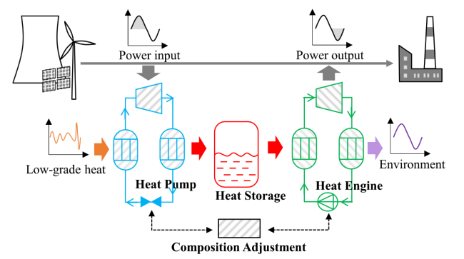
Fig. 1 Schematic diagram of pumped thermal energy storage |
However, the temperature and capacity of low-grade heat source, environment temperature, and input and output power capacity may frequently change with times and seasons. To realize the operating matching between the working fluid compositions of sub-systems and boundary conditions, composition adjustment is introduced to TI-PTES in this study, as Fig. 1 depicts. The specific configuration of the novel proposed composition-adjustable TI-PTES system is illustrated in Fig. 2. There are four sub-systems: heat pump, heat engine, heat storage, and composition adjustment respectively.
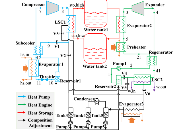
Fig. 2 Configuration of the novel proposed composition-adjustable pumped thermal energy storage |
The heat pump sub-system contains reservoir1, throttle, evaporator1, subcooler, compressor and liquid separation condenser1 (LSC1), as the blue line in Fig. 2 depicts. In charging process, as shown in Fig. 2, working fluid from reservoir1 (10) does isenthalpic throttling and is heated by the low-grade heat in evaporator1 (11-12). Next, working fluid (12) flows to subcooler to further cool working fluid from LSC1. Then, the superheated working fluid (7) is compressed to high pressure with high discharge temperature (8). At last, the high-grade heat of working fluid is delivered to water (8-9) and stored in water tank1.
Sensible heat storage is adopted and water is selected as medium fluid, since the flow rate of water could be controlled stably and flexibly to match the operation of TI-PTES in off-design conditions. Besides, water is natural fluid, environmental-friendly, no-toxic and cheap. For heat storage sub-system, two water tanks are respectively used as low-temperature and high-temperature heat storage tanks. In charging process, low-temperature water in water tank1 is heated (8-9) and pumped to water tank2. In discharging process, the high-temperature water in water tank2 is pumped to water tank1 and heats working fluid in heat engine (5-3).
The heat engine sub-system contains reservoir2, pump1, regenerator, preheater, evaporator2, expander and LSC2, as the green line in Fig. 2 depicts. In discharging process, as shown in Fig. 2, working fluid from reservoir2 is pumped to high pressure (1-2), and respectively heated in regenerator (2-21), preheater (21-5) and evaporator2 (5-3). Next, the high-pressure and high-temperature working fluid (3) expands and exports electricity. Then, the working fluid is condensed by working fluid in regenerator (4-41) and condensed by cooling water in LSC2. At last, the working fluid is stored in reservoir2 and a whole cycle finishes.
2.2 Composition adjustment procedure
To realize flexible composition adjustment of working fluid in heat pump sub-system and heat engine sub-system, liquid separation condenser (LSC) is introduced and a regulating loop is built, as the black line in Fig. 2 depicts. Due to the phenomenon of vapor-liquid equilibrium, vapor composition and liquid composition of working fluid are different when zeotropic mixture is condensed into two-phase zone. Through the application of LSC, the vapor phase and liquid phase could be effectively separated [30], and the initial stream of working fluid (x 1) could be separated into two streams with higher volatile composition (x 3) and lower volatile composition (x 2), as Fig. 3(a) illustrates.
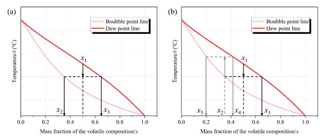
Fig. 3 Temperature-composition diagram during composition adjustment procedure |
Based on the above method, the composition of working fluid could realize a larger adjustment range (x 1 → x 3, x 4, x 5) through the multiple vapor-liquid regulation processes, as Fig. 3(b) depicts. For heat pump as example, the specific procedures of composition adjustment could be realized by the following steps:
● Situation 1: Needing higher volatile composition of working fluid. V5 and V6 remain closed, V2 and V3 are switched on, and V1 is switched off. Then, the original working fluid (x 1) in heat pump is separated into two streams by LSC1, the stream with higher volatile composition (x 3) is stored in tank3, while the stream with less volatile composition (x 2) flows to evaporator3 and is heated into two-phase zone by the low-grade heat. Then, the vapor-liquid mixture is separated in tank5, stream with medium volatile composition (x 4) is stored in tank4 and stream with less volatile composition (x 5) is stored in tank5. As a result, high, medium and low volatile composition of working fluid are respectively stored in tank3, tank4 and tank5. Then, the required composition (x) could be obtained by controlling the running time of pump3, pump4 and pump5 if the value of x is between x 5 and x 3. When x is larger than x 3, the liquid stored in tank3 should be fully pumped to reservoir1, and repeat the above procedure.
● Situation 2: Needing lower volatile composition of working fluid. Most procedures are similar to the situation 1. At the last step, if the required composition (x) is less than x 5, the liquid stored in tank5 should be fully pumped to reservoir1, and repeat the above procedure.
● Situation 3: The operating composition is suitable. V2 and V3 are switched off, V1 is switched on, and LSC1 is equivalent to a standard condenser.
Since the volatile composition of working fluid stored in tank4 is between tank3 and tank5, working fluid in tank4 could be used in the transitory state of regulation. Concretely, pump4 could be turned on first at the start of composition adjustment stage, leading to the accumulation of liquid stored in tank3 and tank5. For example, when the mass fraction of volatile composition of working fluid approaches 0% or 100% while a 50% mass fraction of volatile composition is required in sub-system, the working fluid in tank4 could be charged into sub-system at the start of composition adjustment until tank4 is nearly empty or tank3 or tank5 is full enough.
Similarly, the specific procedures of composition adjustment for heat engine are the same as heat pump. V4, V5 and V6 are equivalent to V1, V2, and V3, respectively. The specific description is omitted here.
2.3 Boundary conditions and fluid selection
In this study, an energy community is selected as the research objective, and abundant low-grade heat from industrial waste water is freely utilized [15]. The varying spread of industrial waste water temperature locates at 50-90 oC and the medium temperature of 70 oC is selected as the design condition. For TI-PTES, temperature lift (which is the temperature difference between low-grade heat and water tank2) through heat pump sub-system is defined as no less than 15 °C and temperature difference between water tank1 and water tank2 (Δt sto) is set as 10, 15, 20, 25, 30 °C. The key design parameters of the composition-adjustable TI-PTES are listed in Table 1.
Table 1 Key design parameters of the composition-adjustable TI-PTES |
| Term | Unit | Value |
|---|---|---|
| Low-grade heat | ||
| Inlet temperature of water | oC | 70 |
| Outlet temperature of water | oC | 50 |
| Heat pump | ||
| Pinch point of evaporator1, LSC1 | oC | 5 |
| Pinch point of subcooler | oC | 10 |
| Isentropic efficiency of compressor | % | 85 |
| Heat storage | ||
| Temperature difference between tank1 and tank2 | oC | 10, 15, 20, 25, 30 |
| Mass flow rate of water | kg/s | 1 |
| Heat engine | ||
| Inlet and outlet temperature of cooling water | oC | 20/30 |
| Subcooling degree in the outlet of LSC2 | oC | 2 |
| Pinch point of preheater, evaporator2, LSC2 | oC | 5 |
| Pinch point of regenerator | oC | 10 |
| Isentropic efficiency of pump, expander | % | 85 |
To guarantee the efficient operation of TI-PTES, temperature difference between the highest heat storage temperature and low-grade heat inlet temperature should be less than 60 °C [14]. Thus, the highest temperature of heat storage is set to no more than 130 °C. Besides, as the temperature spread between water tank1 and water tank2 locates in the interval 10 ~ 30 °C, sub-critical cycles are adopted to heat pump sub-system as well as heat engine sub-system [31], and zeotropic mixture of R1233zde/R600a is selected as working fluid due to the matching critical temperature [32]. The properties of R1233zde and R600a are respectively enumerated in Table 2 and the properties of mixture are obtained by REFPROP 10.0a.
Table 2 Properties of selected working fluids |
| Working fluid | P cri (MPa) | t cri (oC) | GWP | ODP | ASHRAE Safety Classification |
|---|---|---|---|---|---|
| R1233zde | 3.62 | 166.4 | 1 | - | A1 |
| R600a | 3.63 | 134.7 | 20 | 0 | A3 |
3 Mathematic model
In this section, the thermodynamic model of composition-adjustable TI-PTES is formulated, design model and operating model of each component are established, and the solution algorithms for system design and practical operating are developed. To simplify the simulation, several assumptions are considered as follows:
• Pressure drop and heat loss are ignorable in pipes.
• Working fluid depressurizes by isenthalpic state in throttle.
• Pump, turbine and compressor operate by isentropic compression/expansion.
• Working fluid in the outlet of evaporator1 is saturated.
• In design stage, the minimum temperature differences between working fluid and boundary fluid in heat exchangers are no less than pinch points.
• Heat loss in heat storage process is negligible and low-grade heat is abundant.
3.1 Component model of heat pump sub-system
In heat pump sub-system, the low-grade heat transfers to evporator1 first. Then, the high-grade heat is obtained and stored in heat storage sub-system. In evaporator1, low-grade heat contained in water heats working fluid to saturated vapor:
$\begin{array}{c}{Q}_{{\text{evap}}1}={m}_{{\text{hs}}}\cdot \left({h}_{{\text{hs}},{\text{in}}}-{h}_{{\text{hs}},{\text{out}}}\right)={m}_{{\text{HP}}}\cdot \left({h}_{12}-{h}_{11}\right)\end{array}$
The basic geometric parameter of evaporator1 could be evaluated as follows:
$\begin{array}{c}{UA}_{{\text{evap}}1}={Q}_{{\text{evap}}1}/{LMDT}_{{\text{evap}}1}\end{array}$
For practical operating conditions, Eqs. (1 and 2) are always satisfied, while the heat transfer efficiency (UA eavp1) may vary with the operating parameters, an amendatory correlation considering the variation of working fluid properties is employed [33]:
$\begin{array}{c}\frac{{UA}_{{\text{evap}}1,{\text{d}}}}{{UA}_{{\text{evap}}1,{\text{od}}}}=\frac{{\alpha }_{{\text{in}},{\text{od}}}^{-1}+{\alpha }_{{\text{out}},{\text{od}}}^{-1}}{{\alpha }_{{\text{in}},{\text{d}}}^{-1}+{\alpha }_{{\text{out}},{\text{d}}}^{-1}}\end{array}$
$\begin{array}{c}\alpha ={m}_{{\text{f}},{\text{R}}}^{0.8}{C}_{{\text{p}}}^{{\text{n}}}{k}^{1-{\text{n}}}{\mu }^{{\text{n}}-0.8}\end{array}$
where, subscript ‘d’ means system design condition and subscript ‘od’ means off-design condition, subscript ‘in’ means inner fluid of evaporator1 and subscript ‘out’ means external fluid. Besides, C p, k, μ are respectively isobaric specific capacity, thermal conductivity and dynamic viscosity, and n = 0.4 for heat fluid and n = 0.3 for cold fluid.
In subcooler, working fluid in the outlet of LSC1 is precooled:
$\begin{array}{c}{Q}_{{\text{subc}}}={m}_{{\text{HP}}}\cdot \left({h}_{9}-{h}_{10}\right)={m}_{{\text{HP}}}\cdot \left({h}_{7}-{h}_{12}\right)\end{array}$
For practical operating conditions, the working principle of subcooler and other heat exchangers are similar to evaporator1. Thus, the specific equations are omitted in this study.
In LSC1, high-grade heat containing in working fluid transfers to water and is stored in water tank1:
$\begin{array}{c}{Q}_{{\text{sto}}}={m}_{{\text{HP}}}\cdot\left({h}_{8}-{h}_{9}\right)={m}_{{\text{sto}}}\cdot \left({h}_{{\text{sto}},{\text{high}}}-{h}_{{\text{sto}},{\text{low}}}\right)\end{array}$
For throttle, isenthalpic expansion is always satisfied:
$\begin{array}{c}{h}_{11}={h}_{10}\end{array}$
For compressor, the consuming work is calculated by isentropic compression process:
$\begin{array}{c}\left\{\begin{array}{c}{W}_{{\text{comp}}}={m}_{{\text{HP}}}\cdot \left({h}_{8}-{h}_{7}\right)={m}_{{\text{HP}}}\cdot \left({h}_{8{\text{s}}}-{h}_{7}\right)/{\eta }_{{\text{comp}}}={W}_{{\text{in}}}\\ {h}_{8{\text{s}}}={\text{f}}\left({P}_{8}, {s}_{8{\text{s}}}\right)={\text{f}}\left({P}_{8}, {s}_{7}\right)\end{array}\right.\end{array}$
The mass flow rate of compressor is observed by Eq. (9) [27].
$\begin{array}{c}{m}_{{\text{HP}}}={\rho }_{7}{V}_{{\text{comp}}}\omega \left[1-a-b{\left(\frac{{P}_{8}}{{P}_{7}}\right)}^{\frac{1}{\kappa }}\right]\end{array}$
where, ρ, V comp, ω respectively represent the density of working fluid in the inlet of compressor, the displacement and frequency of compressor. Besides, a, b, κ are equal -0.0254, 0.117 and 1.25, respectively.
For R1233zde/R600a zeotropic mixture, the isentropic efficiencies of compressor in operating process are obtained through the analogy of the characteristic curve of R1233zde [23].
3.2 Component model of heat engine sub-system
In heat engine sub-system, working fluid stored in reservoir2 is pumped to high pressure first:
$\begin{array}{c}\left\{\begin{array}{c}{W}_{{\text{pump}}}={m}_{{\text{HE}}}\cdot \left({h}_{2}-{h}_{1}\right)={m}_{{\text{HE}}}\cdot \left({h}_{2{\text{s}}}-{h}_{1}\right)/{\eta }_{{\text{pump}}}\\ {h}_{2{\text{s}}}={\text{f}}\left({P}_{2}, {s}_{2{\text{s}}}\right)={\text{f}}\left({P}_{2}, {s}_{1}\right)\end{array}\right.\end{array}$
For thermodynamic cycle running with zeotropic mixture, the leakage of working fluid may lead to the phenomenon of composition shift, resulting to the decline of system performance [34]. Due to the leakproof structure, the diaphragm piston pump could prevent the leakage of working fluid, thus, it is selected as the supercharging device. The mass flow rate of pump is calculated by the method of volume efficiency [35]:
$\begin{array}{c}{m}_{{\text{HE}}}={\rho }_{1}{V}_{{\text{pump}}}{N}_{{\text{pump}}}\left[1-\theta {\left(\frac{{P}_{2}}{{P}_{1}}\right)}^{\frac{1}{\sigma }-1}\right]\end{array}$
where, ρ, V pump, N pump respectively represent the density of working fluid in the inlet of pump, the displacement and frequency of pump. Besides, θ and σ are equal 0.05 and 1.25, respectively.
The isentropic efficiencies in operating conditions could be obtained according to the characteristic curve of pump [36].
Then, working fluid is heated in regenerator, preheater and evaporator2 by expansion exhaust, low-grade heat and stored heat, as shown in Eqs. (12, 13 and 14). Particularly, the mass flow rate of low-grade heat in preheater (m hs,preh) is no more than the required value in evaporator1 (m hs,evap1).
$\begin{array}{c}{Q}_{{\text{rege}}}={m}_{{\text{HE}}}\cdot \left({h}_{21}-{h}_{2}\right)={m}_{{\text{HE}}}\cdot \left({h}_{4}-{h}_{41}\right)\end{array}$
$\begin{array}{c}\left\{\begin{array}{c}{Q}_{{\text{preh}}}={m}_{{\text{HE}}}\cdot\left({h}_{5}-{h}_{21}\right)={m}_{{\text{hs}},{\text{preh}}}\cdot \left({h}_{{\text{hs}},{\text{in}}}-{h}_{{\text{hs}},{\text{out}}}\right)\\ {m}_{{\text{hs}},{\text{preh}}}{\le m}_{{\text{hs}},{\text{evap}}1}\end{array}\right.\end{array}$
$\begin{array}{c}{Q}_{{\text{evap}}2}={m}_{{\text{HE}}}\cdot \left({h}_{3}-{h}_{5}\right)={m}_{{\text{sto}}}\cdot \left({h}_{{\text{sto}},{\text{high}}}-{h}_{{\text{sto}},{\text{low}}}\right)\end{array}$
For expander, the output work could be calculated as follows:
$\begin{array}{c}\left\{\begin{array}{c}{W}_{{\text{exp}}}={m}_{{\text{HE}}}\cdot \left({h}_{3}-{h}_{4}\right)={m}_{{\text{HE}}}\cdot \left({h}_{3}-{h}_{4{\text{s}}}\right)/{\eta }_{{\text{exp}}}\\ {h}_{4{\text{s}}}={\text{f}}\left({P}_{4}, {s}_{4{\text{s}}}\right)={\text{f}}\left({P}_{4}, {s}_{3}\right)\end{array}\right.\end{array}$
The operating performance of expander is predicted through Stodola’s equation [37] and the mass flow rate of working fluid is obtained by Eq. (16).
$\begin{array}{c}{m}_{{\text{HE}}}={K}_{{\text{s}}}\sqrt{{\rho }_{3}\left({P}_{3}^{2}-{P}_{4}^{2}\right)}\end{array}$
where, K s is the Stodola’s coefficient and always keeps constant.
The isentropic efficiency of expander in operating conditions is obtained by Eq. (17) [38].
$\begin{array}{c}{\eta }_{{\text{exp}},{\text{od}}}={\eta }_{{\text{exp}},{\text{d}}}{\text{sin}}\left[\frac{\pi }{2}{\left(\frac{{m}_{{\text{HE}},{\text{od}}}\cdot {\rho }_{3,{\text{d}}}}{{m}_{{\text{HE}},{\text{d}}}\cdot {\rho }_{3,{\text{od}}}}\right)}^{0.1}\right]\end{array}$
In LSC2, working fluid is condensed to subcooled liquid and a whole cycle finishes.
$\begin{array}{c}{Q}_{{\text{LSC}}2}={m}_{{\text{HE}}}\cdot \left({h}_{41}-{h}_{1}\right)={m}_{{\text{w}}}\cdot {c}_{{\text{w}}}\cdot \left({t}_{{\text{w}},{\text{out}}}-{t}_{{\text{w}},{\text{in}}}\right)\end{array}$
3.3 Performance evaluation and solution algorithm
The working principle of TI-PTES could be divided into three stages: charging, heat storage, and discharging. Therefore, the energy storage efficiency (η PTP) of TI-PTES could be evaluated by the performance of heat pump sub-system and heat engine sub-system:
$\begin{array}{c}{\eta }_{{\text{PTP}}}=\frac{{W}_{{\text{out}}}}{{W}_{{\text{in}}}}=\frac{{W}_{{\text{exp}}}-{W}_{{\text{pump}}}}{{W}_{{\text{comp}}}}=\frac{{W}_{{\text{exp}}}-{W}_{{\text{pump}}}}{{Q}_{{\text{sto}}}}\cdot \frac{{Q}_{{\text{sto}}}}{{W}_{{\text{comp}}}}={\eta }_{{\text{HE}}}\cdot {COP}_{{\text{HP}}}\end{array}$
The energy storage density could be obtained by Eq. (20).
$\begin{array}{c}{\rho }_{{\text{sto}}}=\frac{{W}_{{\text{exp}}}}{{V}_{{\text{sto}}}}={\frac{{Q}_{{\text{sto}}}\cdot {\eta }_{{\text{HE}}}}{{V}_{{\text{sto}}}}=\rho }_{{\text{w}}}\cdot {C}_{{\text{w}}}\cdot {(t}_{{\text{sto}},{\text{high}}}-{t}_{{\text{sto}},{\text{low}}})\cdot {\eta }_{{\text{HE}}}\end{array}$
For given heat storage low temperature (t sto,low) and high temperature (t sto,high), the optimal energy storage efficiency (η PTP) could be seen as the product of the optimal COP HP and the optimal η HE. Therefore, the solution algorithms for system design and operating evaluation could be divided into two segments namely heat pump sub-system and heat engine sub-system, as Fig. 4 depicts.
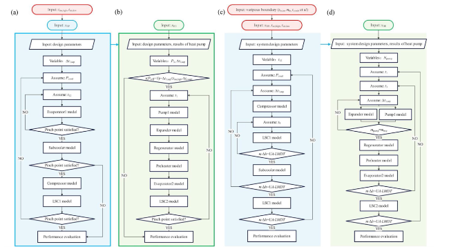
Fig. 4 Flowcharts of solution algorithms. System design flowcharts for: (a) heat pump and (b) heat engine, operating evaluation flowcharts for: (c) heat pump and (d) heat engine |
In system design stage, the main variables contain t sto,low, t sto,high, mass fractions of R1233zde in heat pump sub-system (x HP) and heat engine sub-system (x HE). Other internal variables such as superheat temperature of point 7 (Δt 7,sup), expander inlet pressure (P 3) and superheat temperature of point 3 (Δt 3,sup) are omitted here due to the sufficient study before. The calculation flowcharts of sub-systems could be summarized as the definition of input variables, assumption of operating parameters, sequential solution, hypothesis verification and performance evaluation, as Fig. 4 illustrates. Especially, the given Δt 7,sup may conflict with pinch point of subcooler, resulting in no solution. Therefore, the value of Δt 7,sup should be reset, and the situation is the same for Δt 3,sup. To obtain the maximum COP HP and η HE, particle swarm optimization is employed, the maximum number of iterations is set as 30, and the population size equals 40.
In operating evaluation stage, solution variables contain t sto,low, t sto,high, x HP and x HE, and the calculation flowcharts of sub-systems are similar to the design stage. Particularly, all heat exchangers need to iterate to obtain solution satisfied Eqs. (1 and 2). Since the calculation process is time-consuming and error-prone, method of exhaustion is adopted rather than other algorithms. During the calculation procedure, the convergence factors of mass, temperature and heat transfer capacity in off-design iteration calculation are set as 0.2%, 0.1 °C and 0.5%. In this study, all calculation programs are established in MATLAB 2021a.
3.4 Economic models
$\begin{array}{c}LCOS=\frac{{C}_{{\text{tot}}}+{\sum }_{i=1}^{LS}\frac{{C}_{{\text{an}}}}{{(1+r)}^{i}}}{{\sum }_{i=1}^{LS}\frac{{W}_{{\text{out}}}}{{(1+r)}^{i}}}\end{array}$
where C tot, C an denote the total initial cost and the annual expenditure of TI-PTES. r is the discount rate and is assumed as 5% in this work. LS is the lifespan of TI-PTES and is selected as 25 years. W out is the annual power output capacity.
$\begin{array}{c}{C}_{{\text{an}}}={C}_{{\text{O}}\&{\text{M}}}+{PR}_{{\text{e}}}\cdot {W}_{{\text{in}}}-R\end{array}$
where C O&M is the operating and maintenance cost of TI-PTES during the lifespan. PR e is the electricity price. W in is the annual power input capacity. R is the recover value and is assumed as 0.
$\begin{array}{c}{C}_{{\text{tot}}}=\frac{\sum {C}_{{\text{x}}}\cdot {CEPCI}_{2020}}{{CEPCI}_{2001}}\end{array}$
where C x is the cost of the equipment in TI-PTES. CEPCI 2001 and CEPCI 2001 are 394.3 and 596.2.
The calculation of C x in this study has adopted the method in the authors’ previous work [40] and the details are omitted in this study.
3.5 Model validation
To verify the calculation credibility of TI-PTES in system design stage, model validation is carried out. With the model formulated in this study, the structure of PR-PTES referring to the literature [15] is rebuilt, and R245fa is selected as the working fluid. The relative differences (RD) between simulated results of present model and literature [15] are obtained. As listed in Table 3, relative differences of COP HP, η HE and η PTP are respectively 0.40%, 0.06% and 0.35%, demonstrating sufficient accuracy of the simulation approach used in this study.
Table 3 Validation of the model formulated in this study |
| COP HP | n HE (%) | η PTP (%) | |
|---|---|---|---|
| Reference [15] | 3.954 | 17.44 | 68.96 |
| This work | 3.970 | 17.43 | 69.20 |
| RD (%) | 0.40 | 0.06 | 0.35 |
4 Results and discussion
In this section, optimal system design parameters are obtained first. Then, operating performance of the novel proposed composition-adjustable TI-PTES in various boundary conditions is evaluated and compared with the traditional composition-fixed TI-PTES, and the performance enhancement principle is revealed. At last, a case study concentrating on peak shifting for coal-fired power plant is carried out and the potential of composition adjustment is explored.
4.1 System design results
To evaluate system performance of composition-adjustable TI-PTES in off-design conditions, the construction parameters of system should be acquired first. In this section, the optimal system design parameters are obtained.
In system design stage, there are four critical variables namely t sto,low, t sto,high, x HP and x HE. To investigate the effect of x HP and x HE on energy storage efficiency (η PTP), heat storage temperatures are fixed, concretely, t sto,high is set as 90 °C and t sto,low is set as 75 °C. The optimization result is shown in Fig. 5a, for heat engine sub-system, COP HP increases with x HP first and decreases then, and the maximum value of COP HP is acquired when x HP equals 0.86. For heat engine sub-system, two extremums of η HE are acquired when x HE equals 0.69 and x HE equals 0.95.
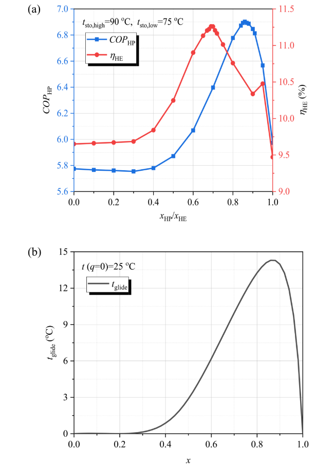
Fig. 5 a Optimal results under given heat storage temperature and (b) temperature glide performance of R1233zde/R600a at condensation temperature of 25 °C |
The above variation is mainly attributed to the performance of thermal match in low-pressure heat exchanging process. Figure 5b shows the variation trend of temperature glide for R1233zde/R600a, and the maximum temperature glide value is obtained as 14.3 oC when x equals 0.86. For heat pump sub-system, the temperature decrease of low-grade heat equals 20 °C, which is larger than 14.3 °C, thus, the best thermal match is obtained when x HP equals 0.86. Similarly, for heat engine sub-system, temperature rise of cooling water equals 10 °C which is less than 14.3 °C. Thus, there are two extremums of η HE and the corresponding x HE is obtained when the corresponding temperature glide locates around 10 oC. Besides, since thermal match performance of evaporation process for x HE equals 0.69 is better than x HE equals 0.95, the optimal η HE is obtained when x HE equals 0.69. As a result, the maximum η PTP is obtained with the maximum COP HP and η HE when x HP equals 0.86 and x HE equals 0.69.
The results obtained in Fig. 5 are acquired when t sto,high equals 90 °C and t sto,low equals 75 °C. For different heat storage temperatures, the best η PTP are different, as shown in Fig. 6a. It should be noted that results shown in Fig. 6 are obtained with optimized x HP and x HE. As Fig. 6a illustrates, for a fixed t sto,low, the value of η PTP decreases with the increase of t sto,high, for a fixed t sto,high, the value of η PTP decreases with the decline of t sto,low. In other words, a small t sto,high and a slight temperature lift (Δt sto) cause a large η PTP. However, as shown in Eq. (20), the energy storage density (ρ sto) increases with growing t sto,high and decreasing t sto,low, which is opposite to the tendency of η PTP, as depicted in Fig. 6b. Generally, the economic performance of TI-PTES is mainly decided by the performance of energy storage density (ρ sto), and a small ρ sto usually results in an enormous investment cost. Therefore, considering η PTP and ρ sto equivalently, heat storage temperatures of 90 °C t sto,high and 75 °C t sto,low are selected as the design parameters, and the detailed system design parameters are enumerated in Table 4.
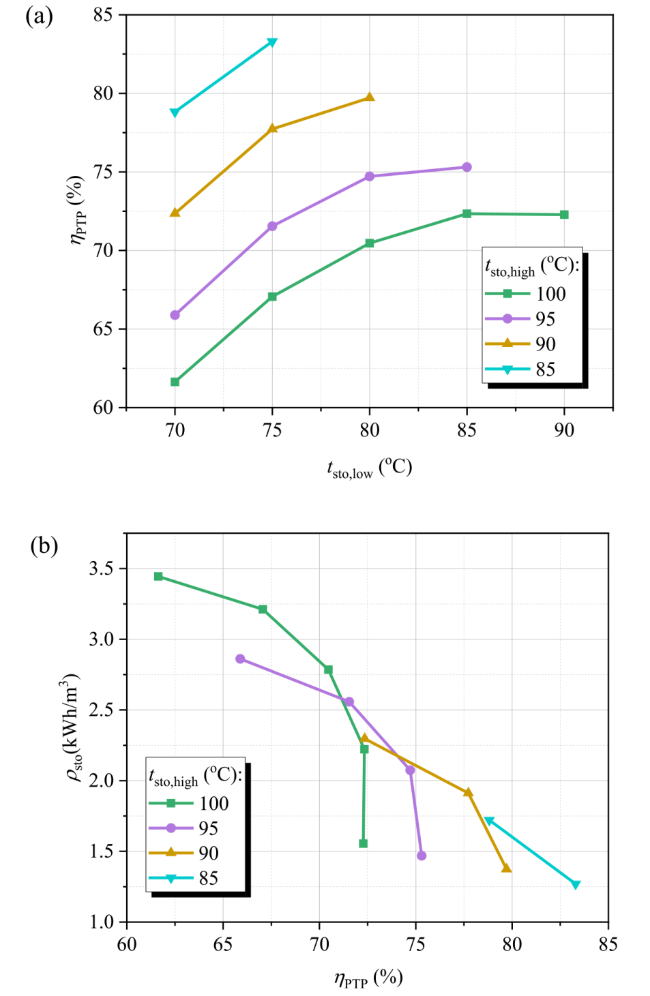
Fig. 6 a Optimal η PTP for different heat storage temperatures and (b) multi-objective optimization for heat storage density (ρ sto) and η PTP |
Table 4 Optimal system design parameters of the novel proposed composition-adjustable pumped thermal energy storage |
| x HP | P LSC1/MPa | P evap1/MPa | t 7/oC | t 8/oC | t 9/oC | t 10/oC | t 11/oC |
|---|---|---|---|---|---|---|---|
| 0.86 | 1.18 | 0.444 | 70.0 | 106.2 | 80.0 | 69.5 | 45.0 |
| t 12/oC | m hs /kg/s | x HE | P LSC2/MPa | P evap2/MPa | t 1/oC | t 2/oC | t 21/oC |
| 54.9 | 0.646 | 0.69 | 0.344 | 1.03 | 25.1 | 25.5 | 31.6 |
| t 5/oC | t 3/oC | t 4/oC | t 41/oC | COP HP | η HE/% | η PTP/% | ρ sto/kWh/m3 |
| 65.0 | 77.2 | 44.7 | 36.5 | 6.90 | 11.3 | 77.7 | 1.91 |
4.2 Operating results under varying boundary conditions
The boundary conditions of TI-PTES contain temperature and capacity of low-grade heat source, temperature of environment, and capacities of input power and output power, as shown in Fig. 1. In off-design conditions, the parameters of low-grade heat source, such as temperature and mass flow rate, may vary with the industrial production load and other influencing factors. Since the construction parameters of heat pump sub-system, such as the structural parameters of heat exchangers and compressor, are determined in design stage, the practical operating parameters of sub-system may vary. As a result, the system performance may significantly change, leading to the unpredictability of the performance of TI-PTES. And the situations are similar for other boundary conditions. In this section, the effect of various boundary conditions on the performance of TI-PTES is investigated.
4.2.1 Various heat source inlet temperature
In this section, the operating performance of composition-adjustable TI-PTES (CA) under various heat source inlet temperature is investigated and compared with composition-fixed TI-PTES (CF).
As shown in Fig. 7a, energy storage efficiencies (η PTP) of CA and CF both increase with heat source inlet temperature (t hs,in), while the values of η PTP for CA are always larger than CF. η PTP of CA could reach 63.4-108.3% with the increase of t hs,in from 50 to 90 oC, which is 4.4-11.1% larger than CF. To pursue a 100% energy storage efficiency, the value of t hs,in for CF needs to be larger than 90 oC, while it only needs low-grade heat of 80 °C for CA. However, the improvement of η PTP for CA is acquired by the sacrifice of heat storage capacity (Q sto), as shown in Fig. 7b, the values of Q sto for CA are always smaller than CF. During the calculation process, the heat storage temperatures are assumed first, thus, the capacity of power input (W in) is a dependent variable and is decided by the boundary conditions and system operating parameters. Figure 7c describes the performance of power input (W in) and power output (W out) with the variation of t hs,in. The consuming capacity (W in) of CA is inferior to CF, while the energy storage efficiency of CA is far ahead of CF.
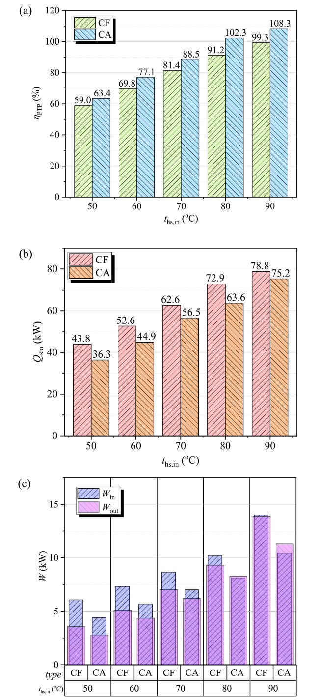
Fig. 7 Operating performance of composition-fixed TI-PTES (CF) and composition-adjustable TI-PTES (CA) under the various heat source inlet temperature (t hs,in): (a) η PTP, (b) Q sto and (c) W in and W out |
The above phenomena of composition-adjustable TI-PTES could be explained from the perspectives of heat pump sub-system and heat engine sub-system. For t hs,in equals 70 °C, t sto,high equals 90 °C and t sto,low equals 75 °C as example, the operating performance of heat pump sub-system is illustrated in Fig. 8. As shown in Fig. 8a, working fluid density in the inlet of compressor (ρ 7) reduces with the increase of x HP, correspondingly, according to Eq. (9), the mass flow rate of working fluid (m HP) decreases since the frequency of compressor keeps fixed in off-design conditions. On the other hand, with the increase of x HP, the mass fraction of R600a decreases. Thus, compression work per mass (w comp = h 8-h 7), latent heat in evaporation (Δh evap1 = h 12-h 11) and enthalpy drop in condensation (Δh LSC1 = h 8-h 9) all decrease. However, the decreasing proportion of Δh evap1 and Δh LSC1 are comparatively slower, as Fig. 8b presents. As a result, the capacities of W in and Q sto both decline with the increasing x HP, as Fig. 7 and Fig. 8 depict. Since the decreasing ratio of W in is larger, COP HP exhibits improvement with the increase of x HP. However, when x HP reaches a relatively large value, the system operates in a far deviation from designing parameters. To achieve the iteration convergence, the solution value (COP HP) may deteriorate, as Fig. 8c presents.
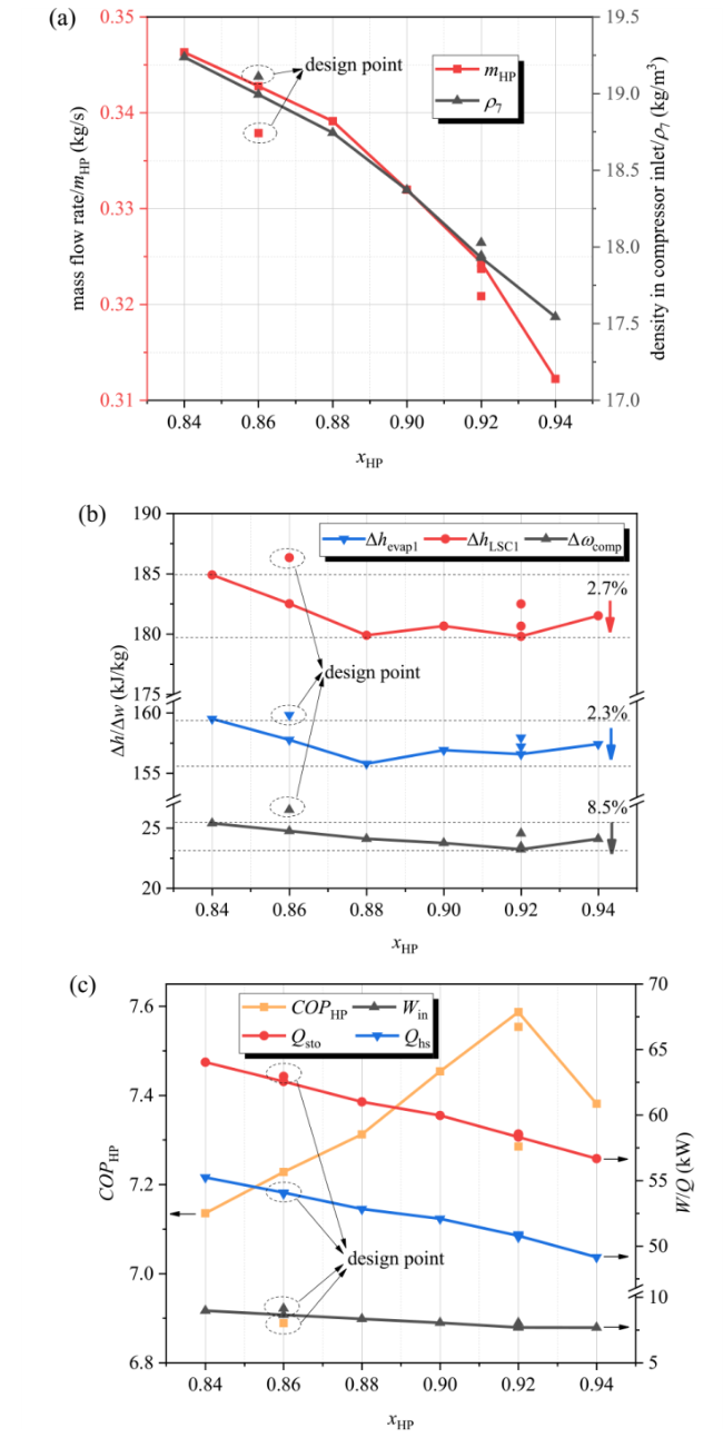
Fig. 8 Operating performance of heat pump sub-system with the variation of x HP when t hs,in equals 70 °C, t sto,high equals 90 °C and t sto,low equals 75 °C: (a) working fluid density in compressor inlet (ρ 7) and mass flow rate (m HP), (b) compression work per mass (w comp), latent heat in evaporation (Δh evap1) and enthalpy drop in condensation (Δh LSC1) and (c) COP HP, Q sto, Q hs and W in |
When t hs,in equals 70 °C, t sto,high equals 90 °C and t sto,low equals 75 °C, the operating performance of heat engine sub-system is obtained, as Fig. 9 describes. As shown in Fig. 9a, the temperatures of all state points are almost fixed, which means the influence of working fluid composition (x HE) on the performance of heat engine sub-system is not remarkable. For heating process in evaporator2, the specific heat capacity (c p,evap2) of working fluid exhibits a slight decline with the increase of x HE. On the other hand, the heating capacity in evaporator2 is fixed as the stored heat. Thus, the mass flow rate (m HE) exhibits an increase with x HE, as Fig. 9b presents. As a result, the power out (W out) of heat engine sub-system improves, η HE could realize an absolute improvement around 0.2%, and the contribution of heat engine sub-system with composition adjustment to η PTP could reach 1.3% as shown in Fig. 9c.
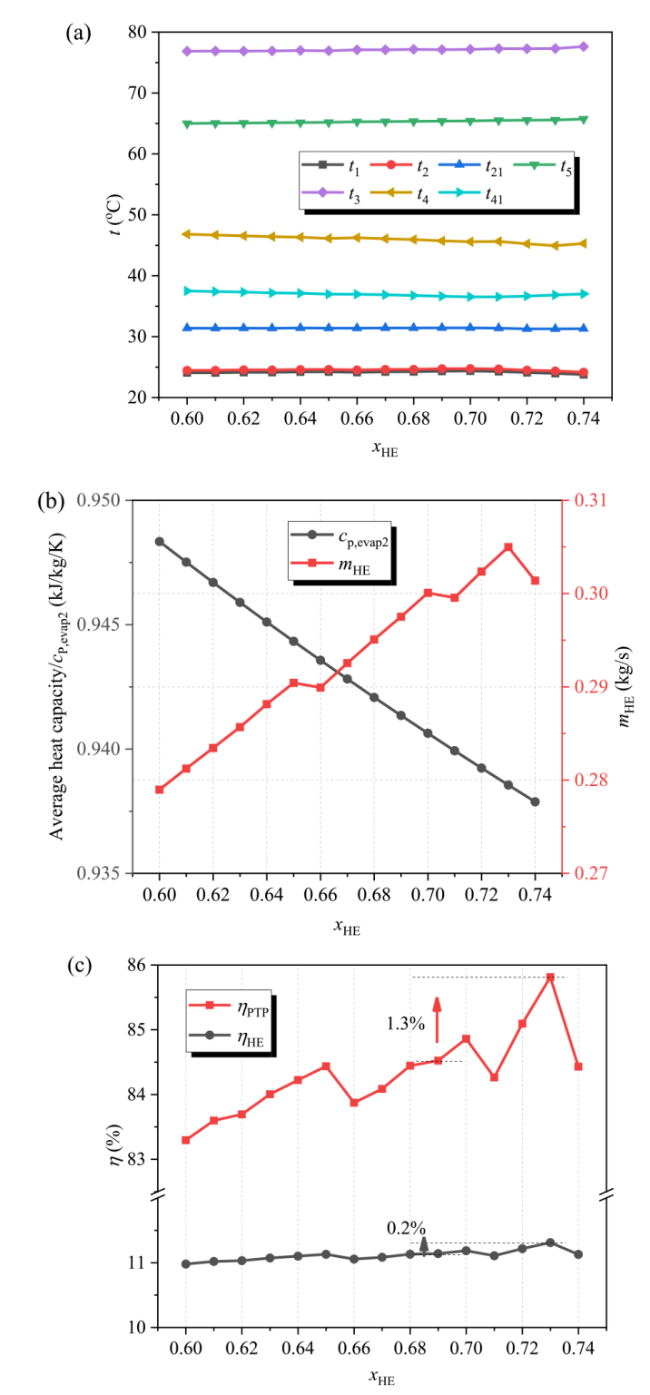
Fig. 9 Operating performance of heat engine sub-system with the variation of x HE when t hs,in equals 70 °C, t sto,high equals 90 °C and t sto,low equals 75 °C: (a) temperatures of all state points, (b) specific heat capacity in evaporator2 (c p,evap2) and mass flow rate (m HE) and (c) η HE and η PTP |
The discussion above is based on the conditions of fixed t sto,high and t sto,low. Particularly, the heat storage temperatures could be artificially controlled to realize the matching operating of TI-PTES under off-design conditions. Figure 10 presents the performance of COP HP, η HE and η PTP under various operating compositions and heat storage temperatures. Generally, for the given heat storage temperatures, the value of COP HP increases with x HP, as depicted in Fig. 10a. With the obtained operating conditions of heat pump sub-system, the performance of heat engine sub-system could be acquired, as Fig. 10b illustrates. Then, the value of η PTP could be calculated by the product of COP HP and η HE, as exhibited in Fig. 10c, and η PTP could realize the maximum value when t sto,low equals 75 °C and t sto,high equals 85 °C. As discussed above, the effect of adjusting x HE on the performance of TI-PTES is less, which means t sto,low equals 75 °C and t sto,high equals 85 °C are the optimal heat storage temperatures. Under the optimized heat storage temperatures, the performance of η HE and η PTP with various x HE could be obtained, as Fig. 10d describes, and the optimal value of η PTP could be obtained as 88.5%. Compared with the optimal value of η PTP obtained with fixed t sto,high and t sto,low, the absolute improvement could reach 2.72%.
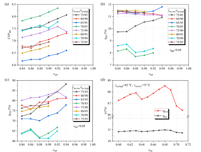
Fig. 10 Performance of composition-adjustable TI-PTES under various operating compositions and heat storage temperatures: (a) COP HP, (b) η HE, (c) η PTP with fixed x HE and (d) η PTP with optimized t sto,low and t sto,high |
In conclusion, for various boundary conditions, the heat storage temperatures could be correspondingly adjusted, and the adjusting range of x HP and x HE could be further enlarged. As a result, the improvement of energy storage efficiency by composition adjustment could be further enhanced.
4.2.2 Various heat source mass flow rate
In off-design conditions, the variation of heat source mass flow rate could lead to the shift of input capacity of low-grade heat in evaprator1, resulting the change of the operating parameters of heat pump sub-system. In this section, the operating performance of composition-adjustable TI-PTES (CA) and composition-fixed TI-PTES (CF) are investigated under various mass flow rate of heat source (m hs), and the relevant results are presented in Fig. 11. Particularly, m hs,od/m hs,d means the ratio of mass flow rate of heat source in operating conditions and design condition.
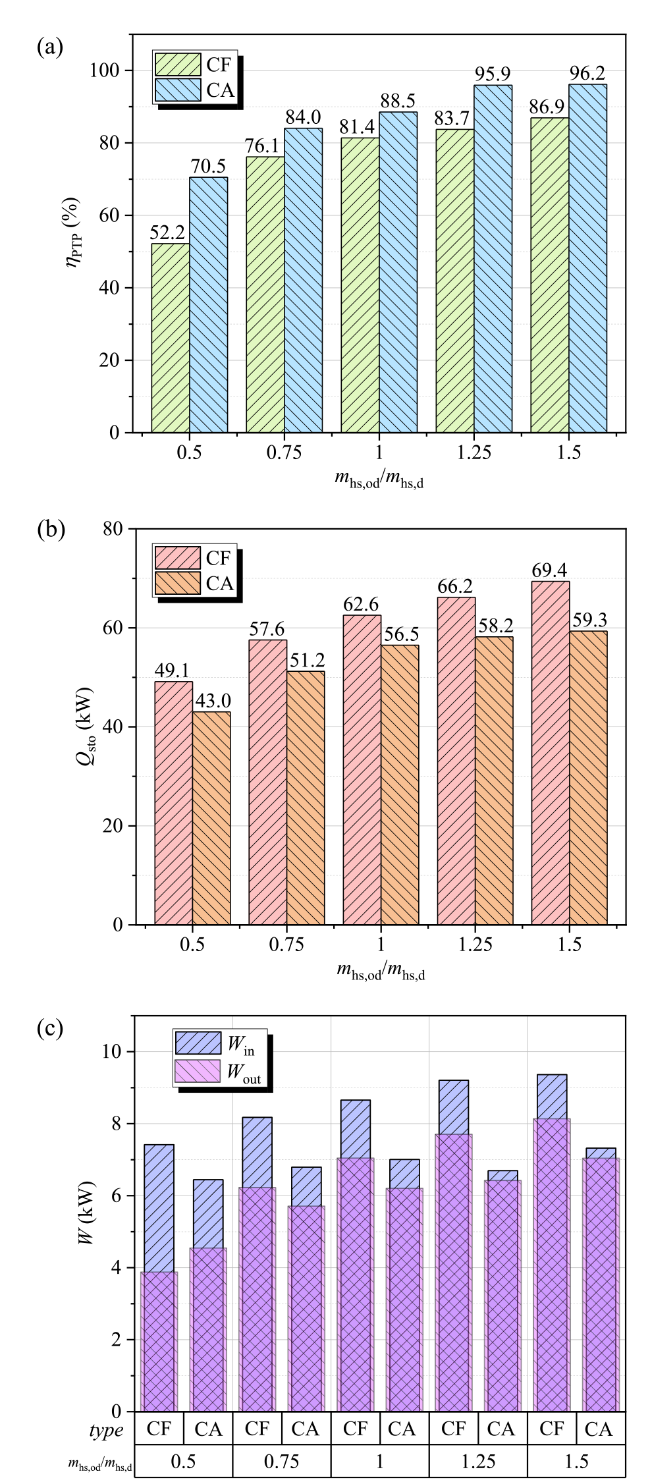
Fig. 11 Operating performance of composition-fixed TI-PTES (CF) and composition-adjustable TI-PTES (CA) under the various heat source mass flow rate (m hs,od/m hs,d): (a) η PTP, (b) Q sto and (c) W in /W out |
As Fig. 11a depicts, energy storage efficiency (η PTP) of CA and CF both increases with the value of m hs,od/m hs,d, the values of η PTP for CA are always larger than CF, especially when m hs,od/m hs,d equals 0.5, and the values of η PTP for CA could reach 70.5-96.2%, which is 7.1-18.3% larger than CF. Particularly, the performance of η PTP for CF deteriorates fast when m hs,od/m hs,d is small, and the value of η PTP only reaches 52.2% when m hs,od/m hs,d equals 0.5. When the value of m hs,od/m hs,d gets large, the growing gradient of η PTP for CF slows down. Similar to the phenomena of t hs,in, the improvement of η PTP for CA under various m hs,od/m hs,d is acquired by the scarification of heating capacity (Q sto). As Fig. 11b describes, the value of Q sto for CA is always smaller than CF. Besides, the required power input (W in) for CA is also smaller than CF, as shown in Fig. 11c.
Similar to the situation of t hs, m hs is another characteristic parameter of low-grade heat source. Thus, the enhancement principle of η PTP by composition adjustment is identical and the detailed explanations are omitted here. Particularly, when m hs,od/m hs,d gets small, such as 0.5, the iteration convergence range of sub-system for CF is limited in a narrow range, and the performance of η PTP occurs a large deterioration. On the contrary, composition adjustment could enlarge the operating range of TI-PTES and achieve a huge improvement of η PTP. In addition, when m hs,od/m hs,d gets large, the quantity of low-grade heat increases while the quality is almost fixed. Since the characteristic parameters of system components are defined in system design stage, the conversion capacity of TI-PTES is limited. As a result, the growing gradients of η PTP for CF and CA both slow down when m hs,od/m hs,d gets large.
4.2.3 Various cooling water inlet temperature of heat engine sub-system
In off-design conditions, the variation of cooling water inlet temperature (t w,in) could lead to the shift of condensation condition in LSC2, resulting the change of the operating parameters of heat engine sub-system. In this section, the operating performance of composition-adjustable TI-PTES (CA) and composition-fixed TI-PTES (CF) are explored under various cooling water inlet temperature of heat engine sub-system (t w,in).
As shown in Fig. 12a, the values of η PTP for CF and CA both increase with the decline of t w,in, and the increment of η PTP for CA is more remarkable when t w,in gets small as the operable range of TI-PTES could be enlarged through composition adjustment. To acquire a 100% energy storage efficiency, t w,in needs to be less than 10 oC for CF, while CA could realize the purpose with t w,in of l5 oC. Since the variation of t w,in only influence the downstream of TI-PTES namely heat engine sub-system, the heat storage temperatures are all fixed for CF and the heat storage capacity (Q sto) is also constant, as Fig. 12b depicts. However, the optimal composition running in heat engine sub-system (x HE) may vary with the heat storage temperatures (t sto,high, t sto,low). Therefore, when t w,in gets large, the best cooperation of x HE, t sto,high and t sto,low for CA occur change, as Fig. 12b presents. Figure 12c describes the performance of power input (W in) and power output (W out) with the variation of t w,in, especially, when t w,in is larger than 30 °C, although the value of W in is smaller, the value of W out for CA is larger than CF, which strongly proves the superiority of composition-adjustable TI-PTES when the operating boundary conditions are far away from the design condition.
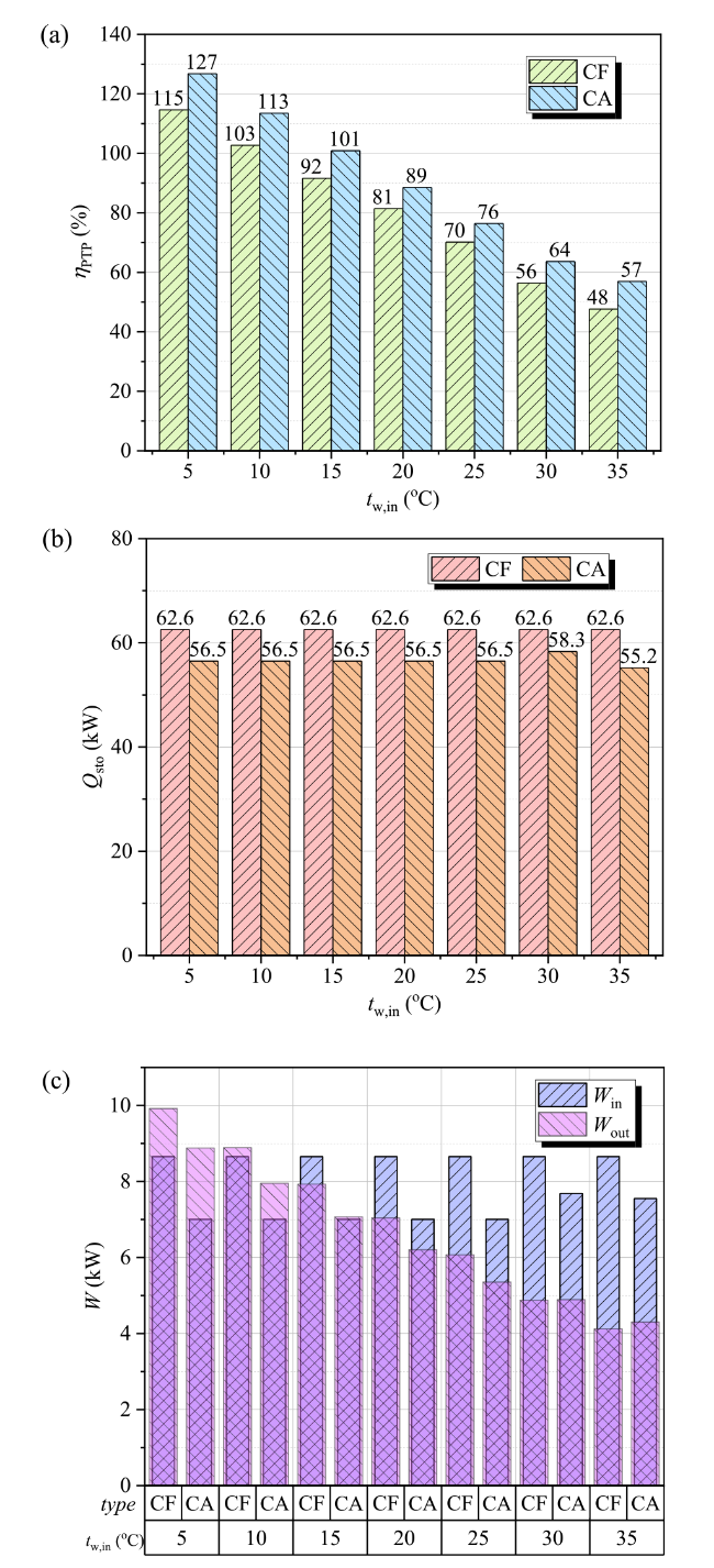
Fig. 12 Operating performance of composition-fixed TI-PTES (CF) and composition-adjustable TI-PTES (CA) under the various cooling water inlet temperature of heat engine sub-system (t w,in): (a) η PTP, (b) Q sto and (c) W in /W out |
4.2.4 Various power input and power output capacities
TI-PTES is mainly used to shave the peak of renewable energy and ensure the safety and stability of grid connection, thus, the power input (W in) of TI-PTES may vary with the power supply of renewable energy. For TI-PTES, the variation of power input (W in) means the quantity of energy storage changes. As discussed above, when the operating boundary conditions change, such as t hs,in, m hs and t w,in, the value of W in correspondingly changes, which means W in is a dependent variable and determined by operating boundary conditions and system characteristic parameters. Since t hs,in and t w,in are related to the quality of power conversion of TI-PTES, m hs is used to investigate the operating performance of power input (W in).
The performance of power input (W in) with the variation of m hs is illustrated in Fig. 13a, particularly, W in,od/W in,d means the ratio of required power input in operating condition and design condition. The performance of W in,od/W in,d is determined by the values of x HP and m hs,od/m hs,d. For composition-fixed TI-PTES, the operating composition of heat pump sub-system (x HP) always equals 0.86 and the variation range of W in,od/W in,d locates at 88-112%, while the values could reach 82-138% for composition-adjustable TI-PTES. As discussed above, the increase of x HP leads to the increase of COP HP and the decrease of Q sto and W in. Inversely, the reduction of x HP leads to opposite results. Similarly, a large W in usually corresponds a small COP HP, as Fig. 13 describes.
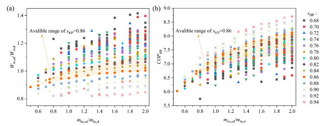
Fig. 13 Performance of heat pump sub-system with different x HP and m hs,od/m hs,d: (a) W in and (b) COP HP |
For heat engine sub-system, similar to W in, the value of power input (W out) is determined by the mass flow rate of high-temperature water (m sto), the relative results are depicted in Fig. 14, particularly, m sto,od/m sto,d represents the ratio of mass flow rate of high-temperature water in operating condition and design condition. It should be noted that the results of CA exhibited in Fig. 14 are optimized with x HE and the values of x HE are different for various m sto,od/m sto,d. As shown in Fig. 14a, the values of W out for CF and CA increase with m sto,od/m sto,d and the available range is similar. When the value of m sto,od/m sto,d is less than 1, the improvement of composition adjustment is tiny, which is similar to the results obtained in Fig. 9. When the value of m sto,od/m sto,d is larger than 1, the improvement of composition adjustment is remarkable. Since the heat storage capacity is given, the performance of heat engine sub-system (η HE) is same as the variation of W out, as Fig. 14b.
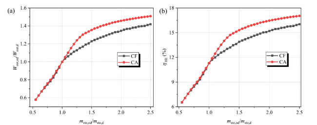
Fig. 14 Performance of heat engine sub-system with different m sto,od/m sto,d: (a) W out and (b) η HE |
4.3 Case study: Electric peak shaving for coal-fired power plant
For an isolated energy community, the power supply from coal-fired power plant is usually fixed, while the consuming load may vary with times [21], as Fig. 15 shows, the power produced capacity is constant, while the required power is lacking during 14:00-4:00 and surplus during 3:00-13:00. A traditional method is to sell electric power during the off-peak stage and buy electric power during the peak stage. However, the electric price is generally fluctuating with time, and the electric price is usually cheap in the off-peak stage and expensive in the peak stage.
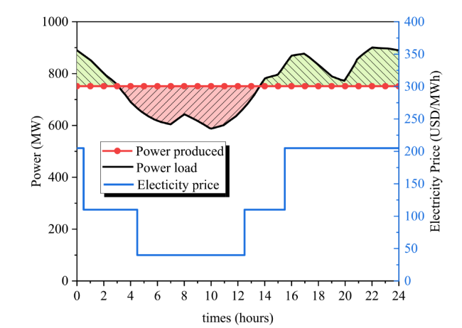
Fig. 15 Daily power produced capacity, power consuming capacity and price of electric power at different times [21] |
To realize the economic maximization, energy storage technology namely TI-PTES is applied. During the off-peak stage, the surplus electricity is imported to heat pump sub-system, and high-temperature water is obtained and stored in water tank1. During the peak stage, the stored heat energy drives heat engine sub-system working and exports electricity to shave the peak power demand. Generally, the off-peak electric power could not be fully converted to heat energy, and the peak electric power may not be fully supplemented by the stored heat energy. Therefore, the actions of buying and selling electric power may still exist.
In this section, the performance of composition-fixed TI-PTES and composition-adjustable TI-PTES are investigated. As depicted in Fig. 16a, during 3:00-13:00, the produced electric power exceeds the demand, for the conventional method, the surplus electric power could be completely sold out, for TI-PTES, the surplus electric power could be converted to heat energy and stored. For composition-fixed TI-PTES, the quantity of power conversion is limited, as shown in Fig. 13a. Therefore, a portion of the electric power remains unutilized and could be sold. For composition-adjustable TI-PTES, the power conversion capacity is better than composition-fixed TI-PTES, and 100% power conversion could be realized, as Fig. 16b presents. During the peak stage, the traditional solution method requires significant electric power purchases, resulting in high costs. For TI-PTES, the stored heat energy could be used to generate electric power, and the discharged electric power could satisfy most power demands, as shown in Fig. 16. Although the improvement of energy storage efficiency for composition-adjustable TI-PTES is acquired by the scarification of heat storage capacity, the flaw could be eliminated in practical application by the integrated management of x HP, x HE, m hs and m sto. As illustrated in Fig. 13, the operating flexibility and COP HP for composition-adjustable TI-PTES in charging process are more competitive, and a higher mass of stored water could be obtained. Besides, the performance of W out and η HE for composition-adjustable TI-PTES in discharging process are superior, as Fig. 14 presents. Therefore, the performance of composition-adjustable TI-PTES is better, as enumerated in Table 5, the application of TI-PTES could remarkably cut down 65.9% daily investment for purchasing electric power, and composition adjustment method could further cut down the cost by 35.6% compared to composition-fixed TI-PTES. Particularly, as enumerated in Table 5, compared with the energy storage technology namely CAES in literature [21], the application of TI-PTES is superior.
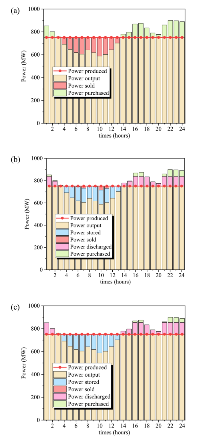
Fig. 16 Electric energy performance of an isolated energy community: (a) Without TI-PTES, (b) with composition-fixed TI-PTES and c with composition-adjustable TI-PTES |
Table 5 Daily investment of different methods for the isolated energy community |
| Methods | Sell/MWh | Buy/MWh | Cost/kUSD | Cost saving percentage /% |
|---|---|---|---|---|
| Without energy storage | -1158.3 | 1158.3 | 161.6 | 0 |
| Reference [21] | -113.0 | 625.2 | 101.3 | 37.3 |
| Composition-fixed TI-PTES | -86.6 | 299.8 | 55.1 | 65.9 |
| Composition-adjustable TI-PTES | 0 | 177.0 | 35.5 | 78.0 |
From the perspective of economic performance, based on the lifespan as 25 years, the total cost of buying electric power could reach 1.48 $\times$ 106 kUSD for the isolated energy community without energy storage. After introducing energy storage method namely composition-fixed TI-PTES, the total cost could be cut down to 1.12 $\times$ 106 kUSD, which contains total initial cost of 6.15 $\times$ 105 kUSD and electricity purchase cost of 5.03 $\times$ 105 kUSD. For energy storage method namely composition-adjustable TI-PTES, the total cost is around 9.8 $\times$ 105 kUSD, which contains total initial cost of 6.56 $\times$ 105 kUSD and electricity purchase cost of 3.24 $\times$ 105 kUSD. The relative results, such as total initial cost (C tot), the Levelized cost of storage (LCOS) and the payback period, are enumerated in Table 6. Although the total initial cost (C tot) is larger for composition-adjustable TI-PTES due to the additional investment of composition adjustment sub-system, the long-term economic performance is better and the payback period is shorter.
Table 6 Economic performance of different energy storage methods |
| Methods | C tot/105kUSD | LCOS/ kUSD/MWh | Payback period/year |
|---|---|---|---|
| Composition-fixed TI-PTES | 6.15 | 0.228 | 15.82 |
| Composition-adjustable TI-PTES | 6.56 | 0.212 | 14.25 |
4.4 Opportunity and challenge
In off-design conditions, the traditional composition-fixed TI-PTES could change the heat storage temperatures to match the varied boundary conditions, while the benefit to system performance is limited. For composition-adjustable TI-PTES, the integrated management of operating compositions in sub-systems and heat storage parameters could further enhance the performance of TI-PTES in off-design conditions. However, the integrated management of system operating parameters to match the boundary conditions is complex and challenging, this study just carries out the preliminary exploration, and further work could be carried out in the following area:
• Construction design of composition-adjustable TI-PTES for various application situations.
• Composition adjustment strategy for sensible heat storage and latent heat storage in off-design conditions.
• Dynamic response characteristic of composition adjustment procedure.
5 Conclusion
In this study, a novel composition-adjustable TI-PTES is proposed and the detailed composition adjustment procedure is established. Then, the operating performance of composition-adjustable TI-PTES under various boundary conditions is investigated and compared with composition-fixed TI-PTES. At last, a case study of utilizing off-peak electricity for peak shaving by TI-PTES is carried out. The main conclusions could be drawn as follows:
(1) The introduction of composition adjustment could remarkably enhance the energy storage efficiency of TI-PTES. Compared to composition-fixed TI-PTES, the absolute improvement rates of composition-adjustable TI-PTES could reach 4.4-11.1% for various inlet temperature of low-grade heat sink, 7.1-18.3% for various mass flow rate of low-grade heat sink, and 6.3-12.2% for various cooling water inlet temperature of heat engine sub-system.
(2) The improvement of energy storage efficiency for composition-adjustable TI-PTES is attributed to the cooperative adjustment of sub-system compositions and heat storage temperatures. Tuning the compositions of sub-systems (x HP and x HE) could adjust the interior operating parameters of sub-systems and increase the performance of sub-systems in operating conditions. Meanwhile, the adjusting range of x HP and x HE could be further enlarged by adjusting the heat storage temperatures.
(3) Tuning the compositions of sub-systems (x HP and x HE) can achieve a more flexible operating range. The adjustment of operating composition in heat pump sub-system (x HP) could simultaneously change the performance of heat pump sub-system (COP HP), power input (W in) and heat storage capacity (Q sto), and the adjustment of operating composition in heat pump sub-system (x HE) could improve the performance of heat engine sub-system (η HE) and power output (W out).
(4) The integrated management of operating compositions in sub-systems and heat storage parameters could enhance the performance of TI-PTES in practical application. For an isolated energy community, the application of TI-PTES could significantly reduce the daily investment for purchasing electric power by 65.9%, and the composition adjustment method could further reduce costs by 35.6% compared to composition-fixed TI-PTES.
6 Nomenclature
c Specific heat capacity (kJ/(kg K))
COP Coefficient of performance
C tot Total initial cost
h Enthalpy (kJ/kg)
LCOS Levelized cost of storage
m Mass flow rate (kg/s)
P Pressure (MPa)
q Quality
Q Heat transfer capacity (kW)
t Temperature (oC)
W Work (kW)
x R1233zde mass fraction of mixture
6.1 Greek symbols
η Efficiency
ρ Density (kg/m3)
Δ Difference
6.1.1 Subscripts
comp Compressor
evap1 Evaporator1
evap2 Evaporator2
exp Expander
d System design state
glide Glide temperature
HE Heat engine sub-system
HP Heat pump sub-system
hs Low-grade heat source
high High
low Low
od Off-design state
preh Preheater
rege Regenerator
sto Storage
subc Subcooler
sup Superheat
w Cooling water
1-5,7-12,21,41 State points
Abbreviations
B-PTES$\ \ \ \ \ \ \ \ $PTES with basic heat pump and basic heat engine
CA$\ \ \ \ \ \ \ \ $Composition-adjustable pumped thermal energy storage
CAES$\ \ \ \ \ \ \ \ $Compressed air energy storage
CF$\ \ \ \ \ \ \ \ $Composition-fixed pumped thermal energy storage
LAES$\ \ \ \ \ \ \ \ $Liquid air energy storage
LSC$\ \ \ \ \ \ \ \ $Liquid separation condenser
OFC$\ \ \ \ \ \ \ \ $Organic flash cycle
ORC$\ \ \ \ \ \ \ \ $Organic Rankine cycle
PHES$\ \ \ \ \ \ \ \ $Pumped hydro energy storage
PR-PTES$\ \ \ \ \ \ \ \ $PTES with regenerated heat pump and preheated regenerated heat engine
PTES$\ \ \ \ \ \ \ \ $Pumped thermal energy storage
R-PTES$\ \ \ \ \ \ \ \ $PTES with regenerated heat pump and regenerated heat engine
TI-PTES$\ \ \ \ \ \ \ \ $Thermal-integrated PTES
V1-V6$\ \ \ \ \ \ \ \ $Ball valve、
Acknowledgements
This work was supported by the Students’ Innovation and Entrepreneurship Foundation of USTC (Grant No. CY2022G35), Youth Innovation Promotion Association CAS (Grant No. 2022463), the USTC Institute for Carbon Neutrality and Joint research center for multi-energy complementation and conversion.
Authors’ contributions
XS conceptualized the study, developed the methodology and software, carried out data analysis and visualization, and wrote the original daft. LS conceptualized the study, developed the methodology, wrote the original daft, and edited the manuscript. MZ participated in conceptualization, investigation, methodology, software, and formal analysis. HT and PH assisted in conceptualization, and review of the manuscript. GP participated in conceptualization, and editing of manuscript. GS supervised the overall project. The final version of the paper has been approved by all authors.
Funding
Open access funding provided by University of Science and Technology of China. This work is financially supported by the Students’ Innovation and Entrepreneurship Foundation of USTC (Grant No. CY2022G35), Youth Innovation Promotion Association CAS (Grant No. 2022463), the USTC Institute for Carbon Neutrality and Joint research center for multi-energy complementation and conversion.
Availability of data and materials
The data and materials are available upon reasonable request.
Declarations
Ethics approval and consent to participate
All co-authors certify that the submission is original unpublished work and is not under review elsewhere.
Consent for publication
All authors agree to the publication of this manuscript.
Competing interests
Gang Pei is an editorial board member for Carbon Neutrality and was not involved in the editorial review, or the decision to publish this article.
Publisher’s Note
Springer Nature remains neutral with regard to jurisdictional claims in published maps and institutional affiliations.
