
1 Introduction
Rapid development of productivity coexists with dual challenges of environmental pollution and energy crisis [1,2,3]. Nowadays, the energy consumption is still dominated by fossil fuels, its characters of non-renewable and fast depletion threaten the survival of next generations (https://ourworldindata.org/fossil-fuels), [4,5]. Therefore, developing new energy technologies and improving efficiency of conventional energy become two cores to address these issues for reducing carbon emissions [6]. The aim of energy conservation and emission reduction urges people to seek environmental-safe alternative energy [7,8]. The proportion of renewable sources such as solar [9], wind [10], geothermal [11] and biomass energy [12] in the energy distribution has increased significantly over the past few decades. Nevertheless, a large amount of heat is still wasted in the energy-related production, distribution and end-use [13,14]. In this background, developing new energy technologies has attracted increasing attention of scholars. Among all feasible technical solutions in dealing with this problem, thermoelectric (TE) devices which are based on Seebeck effect have attracted more and more attention owing to their advantage of direct heat-electricity conversion [15]. Besides, TE devices based on Peltier effect can be used for heating or cooling when they are operated via a direct circuit voltage [16]. These working characteristics of TE devices make them have both functions of power generation and regulating temperature, thus it has the potential to be compatible with other energy systems. TE devices are manufactured with TE materials, and they can operate silently and have no mechanical transmission parts. It is easy to maintain TE devices relying on their character of long service life and reliable performance [17,18,19]. Compared with other energy conversion devices, TE devices with compact structure are applicable for many energy applications. In particular, they have been widely used in many fields such as comprehensive utilization of solar energy [20], waste heat recovery [21], aeronautics and astronautics power supply [22], temperature control [23,24] and signal monitoring [25], etc. If TE devices can be appropriately employed, it will bring new opportunities to improve energy efficiency and expand the scope of application.
TE devices are generally categorized into thermoelectric generator (TEG) and thermoelectric cooler (TEC) based on working principles of Seebeck effect and Peltier effect, respectively. The illustration of TE device, working mechanisms of Seebeck effect and Peltier effect are shown in Fig. 1. The Seebeck effect was independently discovered in 1821 by German physicist Thomas Johann Seebeck (http://thermoelectrics.matsci.northwestern.edu/thermoelectrics/history.html). The general phenomenon can be described as follows. If a closed loop is formed by two different conductors joined in two places, an electric current will be generated in the closed loop when a temperature difference is given between the two junctions [15]. This is because there are differences in the carrier (electron or hole) mobility of different TE materials (usually metals or semiconductor materials) at different temperatures [26]. When a temperature difference is applied to the two junctions, a potential difference will be created between the junctions, which in turn produces an electric current through the wires. The Peltier effect was discovered in 1834 by French physicist Jean Charles Athanase Peltier (http://thermoelectrics.matsci.northwestern.edu/thermoelectrics/history.html). The Peltier effect can be considered as the reverse process to the Seebeck effect. When an electric current is passed through the simple closed TE circuit (i.e. the closed loop in Seebeck effect), the electric current will drives heat released at one junction and absorbed heat at the other junction [15]. The reason for this phenomenon is that Fermi energies (a concept in quantum physics related to the energy state of occupied electrons at temperatures above zero) between the jointed TE materials are different [27]. The property of TE materials and the junction temperatures determine the capacity of the heat absorption or release. Obviously, the property of TE materials and temperature conditions are key factors that determine the performance of TE devices.
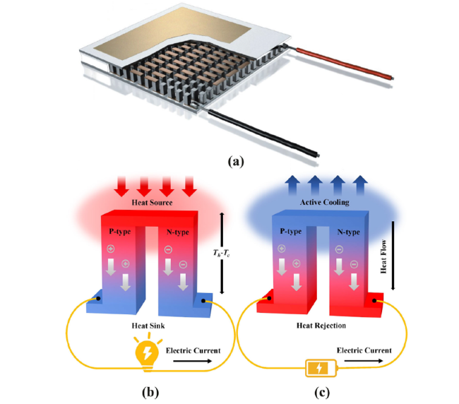
Fig. 1 a Illustration of TE device (http://www.ferrotec.com.cn/en/products/productinfo/84.html); Mechanisms of b Seebeck effect and c Peltier effect |
For a long time, researchers focus on developing TE materials with superior performance. The property of TE materials is generally evaluated using the figure of merit (i.e. ZT, a dimensionless parameter), ZT can be calculated by Eq. (1) [28].
$ ZT=\frac{S^2\sigma }{\kappa }T $
It can be seen that the factors that determine the quality of ZT are S (Seebeck coefficient), σ (electrical conductivity), κ (thermal conductivity) and T (temperature), respectively. κ is comprised of two separate thermal parameters κe (electronic thermal conductivity) and κl (lattice thermal conductivity). Accordingly, improving the property of TE material need to increase S and σ while reduce κ, which can reduce the Joule heat loss and slow down the heat conduction between hot and cold ends of TE material, so that the TE devices can obtain better performance [29]. Three thermoelectric parameters S, σ, and κ are coupled with each other and are closely related to T. In order to pursue high ZT, researchers have developed a series of new TE materials with high-performance by adjusting the material ratio, optimizing the dimension, structure and preparation process [30,31,32,33,34,35,36]. Since the TEG is regarded as a power generation engine and the TEC is regarded as a refrigerator, the performance of TEG and TEC can be evaluated as efficiency (η) and coefficient of performance (COP). Based on the non-equilibrium thermodynamics, the maximum efficiency of TEG (ηmax) and the maximum COP of TEC (COPmax) can be calculated by Eq. (2) and Eq. (3):
$ {\eta}_{\mathrm{max}}=\frac{T_h-{T}_c}{T_h}\times \frac{\sqrt{1+{ZT}_{avg}}-1}{\sqrt{1+{ZT}_{avg}}+\frac{T_c}{T_h}} $
$ {COP}_{\mathrm{max}}=\frac{T_c}{T_h-{T}_c}\times \frac{\sqrt{1+{ZT}_{avg}}-\frac{T_c}{T_h}}{\sqrt{1+{ZT}_{avg}}+1} $
where Th and Tc indicate the hot side temperature and the cold side temperature, respectively. Tavg denotes the average of Th and Tc. According to Eqs. (2) and (3), if ZT is considered as infinite value, ηmax or COPmax are infinitely close to the Carnot energy conversion ratio [37,38]. TE devices can be regarded as a Carnot engine which the operating medium are electrons. However, limited by the manufacturing techniques and economic costs, the ZT of commercial available TE materials (such as bismuth telluride, skutterudite, etc.) are still much less than 3 at present [39,40,41]. In fact, the limitation of TE materials properties not only make TE devices difficult to realize industrialization, but also restrict the practical application range of TE system. In view of this actuality, it has become an inevitable choice to improve the performance of TE system by optimizing external working conditions.
TE systems have been used as TEG or TEC respectively for power generation or temperature regulation. A conventional TEG system generally includes heat source, TEG and heat sink. In regard to electric energy production of TEG system, it is directly related with performance of TEG and working temperature difference. Except for improving the performance of TEG, optimizing and regulating the thermal management are equally important to enhance efficiency and improve performance of TEG systems [42]. TEC system is the refrigerator mode of TE system. A conventional TEC system typically includes TEC and direct-current power. Similarly, the application of TEC system in control temperature is restricted to the limited cooling capability of TEC and thermal conditions. Therefore, it is also necessary to optimize the thermal management for improving COP of TEC system [43]. In summary, it will be hopeful of improving the performance of TE systems if the thermal management can be well coordinated.
Actually, TE systems often face with temperature fluctuation in practical applications [44]. Especially in waste heat recovery and new energy power generation, there is always a disconnect between demand and supply. That is the mismatch of energy acquisition and storage in time and space caused by instability and intermittentness. Endeavor of thermal management with phase change materials (PCM) may offer a credible solution. As one of the core components of thermal management, PCM has advantages of large heat storage density and good thermal stability. It can absorb and release heat during the phase change process without significant temperature change. This makes the thermal management based on PCM gradually develop into an ideal method for peak clipping, valley filling and energy storage. Therefore, thermal management based on PCM can help TE system obtain relative stable temperature conditions, and give full play to the potential of TE system in thermoelectric conversion and temperature adjustment. TE system expands the energy conversion path between primary energy and secondary energy through heat-electric reversible conversion. However, TE system is very dependent on external conditions (such as temperature difference, current intensity, etc.) during operation. As a result, the transient characteristic of TE system restricts its application scenarios. Thermal management based on PCM not only makes thermal energy allocation more reasonable, but also prolongs service time and indirectly improves efficiency through off-peak heat use. Moreover, the temperature of PCM is almost steady during its process of store or release latent heat. This will help to slow down the unwanted performance degradation of TE system due to transient temperature changes. It is not difficult to recognize that the thermal management based on PCM perfectly meets requirements of TE system. According to the characteristics of PCM and TE device, researchers have constructed a series of novel TE systems coupling with PCM (TE-PCM system) through optimizing design in order to achieve rational energy utilization. Compared with conventional TE system, TE-PCM systems have the potential not only to obtain better output performance, temperature control and expand applicable fields, but also to extend the energy harvest and conversion duration. Meanwhile, the compatibility of TE-PCM systems with other energy systems have also been further developed.
This article reviews recent advances and development prospects of TE-PCM systems. The sections are organized as to serve both of academic research and system implementation. This review summarizes the TE-PCM system from five sections according to R&D background, configuration principle, application actuality and design optimization, future outlook and analysis summary. Section 1 gives a brief on the fundamental of TE technology and a general introduction on TE systems with the application of PCM in thermal management. Section 2 presents a general overview on configuration types and characteristics of TE-PCM systems. Section 3 describes the current state of art for TE-PCM systems in application development and design optimization. Section 4 indicates some priority research direction in TE-PCM systems that should be addressed in order to make this technology technically and economically viable. Finally, this review concludes with a concise summary in Section 5. This article would provide a valuable reference for future research on the TE-PCM systems and their applications.
2 Configuration types and characteristics
Complex working conditions require PCMs to play different roles in TE-PCM systems to achieve the energy optimization. This not only determines configuration type of TE-PCM systems, but also makes the characteristics of TE-PCM systems different from TE systems no matter they are in power generation mode or refrigeration mode. In order to better understand the working mechanism of TE-PCM systems, the theoretical model of TE-PCM systems used for simulate their transient behavior during the heating and cooling stages is summarized, as originally developed in Refs. [45,46,47]. In the transient thermoelectric problem, the heat transfer equation, the electric current density and continuity of the electric current are coupled as follow [48]:
$ \rho {C}_p\frac{\partial T}{\partial t}+\nabla q=Q $
$ \nabla J=\frac{\partial {\rho}_c}{\partial t} $
where ρ, Cp, q, and Q in Eq. (4) in turn indicate the density of TE device, the specific heat capacity of TE device, heat flux by Fourier heat conduction and Peltier heat, and internal heat generation. J and ρc in Eq. (5) represent electric current density and charge density, respectively.
The heat flux and relation between the electric current density and the electric field (E) can be expressed as [49]:
$ q=-\kappa \nabla T+ PJ $
$ Q= JE $
where Peltier coefficient (P) and flux of the electric current are coupled by the irreversible Joule and reversible Seebeck effects. V in Eq. (9) denotes voltage.
$ P= ST $
$ J=-\sigma \nabla V-\sigma S\nabla T $
The governing equations can be expended by substitution of Eqs. (6), (7), (8) and (9) into Eq. (4) and Eq. (5):
$ \rho {C}_p\frac{\partial T}{\partial t}+\nabla \left(-\kappa \nabla T+ ST\left(-\sigma \nabla V-\sigma S\nabla T\right)\right)=\left(-\sigma \nabla V-\sigma S\nabla T\right)\left(-\nabla V\right) $
$ -\sigma \left({\nabla}^2V+S{\nabla}^2T\right)=\frac{\partial {\rho}_c}{\partial t} $
The phase transition process of PCM is modeled by using the energy equation [50]:
$ {\rho}_{PCM}{C}_{p, PCM}\frac{\partial T}{\partial t}+{\rho}_{PCM}{C}_{p, PCM}u\nabla T=\nabla \left({\kappa}_{PCM}\nabla T\right) $
where ρPCM, Cp,PCM, u and κPCM in Eq. (12) in turn indicate the density, specific heat capacity, velocity and thermal conductivity of PCM. Cp,PCM with the inclusion of latent heat for the period of the melting of PCM using apparent heat capacity technique can be determined as given in Eq. (13), where Lf and α represents the latent heat capacity and the change of mass fraction of PCM [51], (https://www.comsol.com/blogs/phase-change-cooling-solidification-metal/).
$ {C}_{p, PCM}=\frac{1}{\rho_{PCM}}\left[\left(1-\theta \right){\rho}_{PCM, solid}{C}_{p, PCM, solid}+{\theta \rho}_{PCM, liquid}{C}_{p, PCM, liquid}\right]+{L}_f\frac{\partial \alpha }{\partial T} $
It is assumed that the phase change of PCM takes place around Tm (melting point of PCM). The phase of PCM in the range of Tm is modeled by the smooth phase transition function θ, which represents the fraction of phase before the transition. The value of θ is zero when PCM in solid state and is equal to unity when PCM in liquid state. The change of mass fraction α is defined by Eq. (14), and ρPCM, κPCM can be expressed as Eq. (15) and Eq. (16):
$ \alpha =\frac{1}{2}\frac{\left(1-\theta \right){\rho}_{PCM, solid}-{\theta \rho}_{PCM, liquid}}{\rho_{PCM}} $
$ {\rho}_{PCM}=\left(1-\theta \right){\rho}_{PCM, solid}+{\theta \rho}_{PCM, liquid} $
$ {\kappa}_{PCM}=\left(1-\theta \right){\kappa}_{PCM, solid}+{\theta \kappa}_{PCM, liquid} $
Finally, the boundary conditions are assumed and fixed as constant energy input (Qin) and convection condition on the one side of TE device. Then the electrical energy or cold energy converted from TE device (W) can be obtained after inputting physical parameters of TE device and PCM in the finite element method numerical simulation software (such as ANSYS, COMSOL Multiphysics etc.) [52,53]. The efficiency of TE-PCM systems (η) is defined as the ratio of W and Qin, which is a percentage of energy utilization and expressed as Eq. (17).
$ \eta =\frac{W}{Q_{in}} $
In this section, TE-PCM systems are categorized and discussed according to the deployment of PCMs. According to practical application scenarios of TE-PCM systems, PCM is placed on one side (hot side or cold side) or two sides of TE device. In terms of above relative positions between PCM and TE device (suppose that the left of “/TE/” refers to the hot side and the right refers to the cold side), we define these three configuration types as “PCM/TE”, “TE/PCM”, and “PCM/TE/PCM”. Figure 2 shows the schematic diagrams of structures in these three configuration types of TE-PCM systems. According to the role and working mechanism of PCM in TE-PCM systems, the main advantages and disadvantages of three configuration types are presented in Table 1. The characteristic details of “PCM/TE”, “TE/PCM”, and “PCM/TE/PCM” are further summarized below.
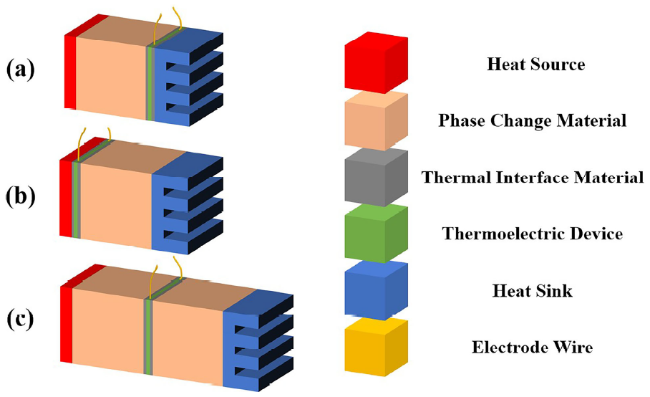
Fig. 2 Schematic diagram of the structure in three configuration types of TE-PCM system: a PCM/TE, b TE/PCM, c PCM/TE/PCM |
Table 1 Main advantages and disadvantages of three configuration types for TE-PCM systems |
| Configuration type | Advantage | Disadvantage |
|---|---|---|
| PCM/TE | • High temperature waste heat recovery • No interference from reverse current • Sensitive thermal response | • High cooling requirements |
| TE/PCM | • Low temperature waste heat recovery or temperature adjustment • Low cooling requirements and even only with PCM | • Having interference from reverse current |
| PCM/TE/PCM | • Waste heat recovery over a wide temperature range • Excellent total power generation | • Slow thermal response • Requiring a large difference in thermal properties of PCM |
2.1 PCM/TE
PCM/TE means the configuration type where the PCM is placed between the heat source and the hot side of TE device. The details of PCM/TE working principle is as follows. It is assumed that initially the PCM is in the solid state. When the temperature of heat source rises, a large amount of thermal energy from heat source can be stored in the PCM. The temperature of PCM will increase until it reaches the melting point. During the phase transition, PCM changes from solid to liquid and the temperature of PCM can remains stable due to fusion enthalpy. Therefore, a large and stable temperature difference between the PCM and heat sink is created, and more electrical energy can be generated by the TE device. When the temperature of heat source falls, the PCM functions as a new heat source and the TE device can then continue to generate electrical energy by using latent energy stored in the PCM. The total amount of heat converted by TE device into electricity come from two parts: the heat provided by heat source and the latent heat supplied by PCM. It can be concluded that the use of PCM improves the energy conversion efficiency. The working mechanism of PCM/TE clearly shows the use of PCMs has significant advantage in case of discontinuous heat supplying. Some studies have been conducted under the guide of this scientific method. A mathematical model of TEG coupled with PCM and preliminary analysis of affecting factors was presented by Wang et al. [54]. The calculation results prove that using appropriate PCM can significantly improve the output power and efficiency of a TEG. Jo et al. proposed a TEG embeds PCM in its device structure which contacts with heat source for waste heat harvesting [55]. Owing that the dissipated heat from heat source was stored by PCM, the output voltage decreased slowly when the heat source was removed. Thus, the TEG with PCM can maintain power generation for longer time under same condition. Rezania et al. investigated the critical parameters and evaluated the energy harvesting performance of a TEG-PCM system [45]. Experimental results show that when 540 kJ thermal energy was applied to the system for 1800 s, a maximum average conversion efficiency of 4.28% was obtained during 6000 s of heating and cooling stages. Accordingly, influence of the all studied factors on the efficiency of system were ranked as follow: length to height ratio of TEG legs > heat source thermal power > thermal resistance of heat sink > PCM type > length to width ratio of PCM. Since the TE-PCM system is periodically subjected to heat flux from external heat sources, hence PCM/TE is usually used to generate a continuous electrical energy when the heat source is on-off. Therefore, PCM/TE is mostly used in waste heat recovery or combined with solar thermal (ST) absorption and conversion system.
2.2 TE/PCM
TE/PCM means the configuration type where the PCM is placed between the cold side of TE device and heat sink (some cases are PCM was embedded into heat sink or only the PCM contacts with the cold side of TE device). Even though the working principle of TE/PCM is similar with PCM/TE, there still have a few differences between these two configuration types. For the purpose of increasing electrical energy generation and enhancing efficiency of TE-PCM system, the key is appropriately using PCM to increase the temperature difference between two sides of TE device. PCM/TE focuses on the dissipated heat reserve and recovery, whereas TE/PCM emphasizes operating at optimal working temperature and guiding heat from heat source to heat sink while generating electricity. Using PCM initially as heat sink is worthy because the PCM does not need any cooling energy in TE/PCM. The constant thermal charging and discharging characteristics of PCM can be exploited for the removal of heat from the cold side of TE device. To make use of PCM is regarded as passive cooling method. The working temperature of TE device can be effectively controlled by guiding the heat rejection from its hot side to cold side. Besides, the temperature difference between heat source and heat sink in TE/PCM is also incidentally increased, which in turn increases the electrical energy and COP. In turn, when the heat source stops supplying thermal energy (for example, there is no solar radiation at night), the PCM functions as new heat source to provide thermal energy by releasing previous stored heat. Related studies by means of this scientific method have shown the potential for improving performance. Riffat and Omer et al. carried out studies to develop a prototype of TEC-PCM system, and investigated the potential application of heat pipe and PCM for thermoelectric refrigeration [56,57]. They employed an encapsulated PCM in place of the conventional bonded fin heat sink unit and contacted it with the cold side of TEC. At the same time, heat pipe embedded fins were also used for heat dissipation at the hot side of TEC. The results proved that the PCM provided powerful storage capability that would be particularly useful for handling peak loads and overcoming losses during power on-off periods. Moreover, TEC-PCM system integrated with thermosyphon diodes that allow the heat flow in one direction further helps cold junction and cabinet temperatures to keep constant for longer time, thereby enhancing the COP. TEC system using PCM for cooling have been numerically simulated by Trelles et al. [58]. The hot side of TEC is connected to a heat sink in order to remove heat from system, while the cold side contacts with the thermostatic unit for keep cooling. This approach is designed for vaccine conservation in TEC-PCM system powered by solar energy. Jaworski et al. design a TEG system made use of radiative heating as heat source and passive cooling by PCM [59]. The results confirmed the potential of the application of PCM as a cooling/heating media for TEG. They also suggest that radiative heating could be switched to radiative cooling and allow utilization of latent heat released from PCM in a reverse phase of the cycle. Consequently, TE/PCM is mostly combined with photovoltaic (PV) conversion system. This hybrid system not only operates at day and night, but also reduces PV power loss caused by temperature rise [60]. Additionally, according to the finding that the decrease in hot side temperature of TE device can decrease its cold side temperature, it results in cooling performance improvement of TE/PCM when TE device operates in refrigeration mode [53]. Therefore, TE/PCM is also used for adjusting the temperature.
2.3 PCM/TE/PCM
PCM/TE/PCM means the configuration type where different kinds of PCMs contact with two sides of TE device respectively. It may be regarded as a combination of PCM/TE and TE/PCM. PCM/TE/PCM is designed as a reusable energy harvesting system that can recover discarded thermal energy by utilizing temperature variation of the environment. It aims at enhancing the amount of released heat of fusion and power generation time duration. PCM/TE/PCM is capable of acquiring diverse temperature differences at different time. The essential of working principle is that PCMs with different thermophysical properties contribute to create different temperature gradients between the two sides of TE device. Specially, PCM/TE/PCM is promising to generate more electricity during phase transition of the PCMs. Afterwards PCM/TE/PCM achieves the purpose of increase electrical energy and prolongs power generation time duration. Some preliminary studies have been carried out based on the combination of the idea involving PCM/TE and TE/PCM. A series of experiments by using PCMs with different thermophysical properties between two sides of TEG have been conducted by Atouei et al. [61]. Compared to the common TEG system without PCM, it not only significantly mitigates the effect of fluctuation of heat input, but also helps long-term power generation by TEG under fixed thermal boundary condition. Liao et al. using different types of paraffin composites as PCM to couple with TEG systems [62]. They reported that a TEG system with double-PCM was built and tested in an environment within the range of 0-40 °C for 3 days. The experimental results show that an increase in the average output power by 35.8% has been obtained by TEG system using double-PCM compared to that using single-PCM. Borhani et al. carried out a numerical investigation to verify the performance improvement of a TEG system by using two different PCMs based on paraffin (RT69 on the hot-side and RT35 on the cold-side) [63]. Paraffin was dispersed into copper porous medium with different porosities and different pores per inches (PPI). The results indicated that the performance of TEG system was enhanced by increasing PPI and reducing porosity. Maximally generated electricity was estimated at low porosity of 0.8 and high PPI of 40. It is not difficult to find that the proposed design makes PCM/TE/PCM perform better over a large temperature range from above representative research works. It is more suitable for the self-power supply applications of small electronic devices (such as wireless sensors) when the heat source cannot provide steady thermal energy.
3 Application development
3.1 TEG-PCM
TEG-PCM systems show great potential in terms of waste heat recovery and compatible co-production with other energy sources. The most prominent practical applications of TEG-PCM systems are traffic (vehicle, aircraft, vessel etc.) and coupling with photovoltaic system and solar thermal cogeneration. Following details are a summary of design ideas and relevant applications.
3.1.1 Traffic
With regard to the applications of TEG-PCM systems for waste heat recovery and utilization, it has shown great potential and development prospects in the field of traffic and transportation such as automotive vehicle, aircraft, vessel, underwater glider etc. Following details are the summaries of several representative efforts taking advantage of TEG-PCM systems.
In the exhaust waste heat recovery of automotive vehicle, TEG has attracted increasing attention because its characteristics of solid-state and light-weight, lower mechanical complexity, and potentially providing higher reliability than other conversion options. In-depth analysis of thermoelectric automotive exhaust waste heat recovery including the impact of thermoelectric materials and thermal interface conditions can be found in Refs. [66,67,68,69], and an overview of design techniques can be found in Refs. [21,70,71]. Automotive exhaust waste heat recovery as one of the few thermoelectric power generation applications, makes sense relative to more mature conversion technologies. The mechanical substitutes are greatly reduced at this power level. Various driving conditions of the motor vehicles and fluctuating temperature of the exhaust waste heat are crucial factors that obstruct the development of automotive TEGs. Figure 3 exhibits representative applications of thermoelectric power generation in automotive vehicles. Because the heat emission during operation has highly transient properties, automotive TEGs are intended for a particular operating state (design point). Transient heat flux brings uncertainty to the optimum operation point of automotive TEGs. There are two major non-ideal scenarios confronted by automotive exhaust waste heat recovery in a real driving situation. Firstly, when the combustion engine runs at loads below the design point, the maximum operating temperature potential of the flue gas cannot be properly utilized. Secondly, when the combustion engine operates at loads above the design point, a bypass is used to divert a subsequently unused portion of the mass flow to protect TEGs, resulting in a waste of thermal energy. The expected variation in both of flue gas temperature and mass flow means that both of the hot-side temperature of a TEG and the magnitude of any thermal gradients will show wide variation over a realistic drive profile. TEGs would likely be in non-optimal state and operate under low efficiency for a majority of its service life.
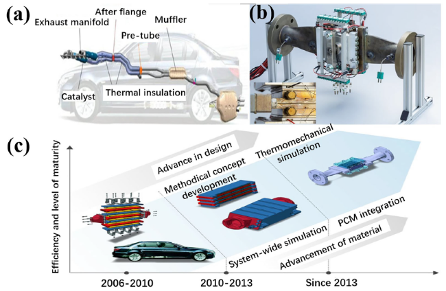
A well-designed thermal buffer based on appropriate PCM is promising for the TEG to maintain operating at the design point (i.e. optimal performance temperature and flue mass flow) for as long as possible. Jankowski et al. confirmed the prospect of applying PCM in automotive exhaust waste heat recovery through reviewing the use of latent heat thermal energy storage for thermally buffering of motor vehicle systems [72]. Therefore, it is recommended that coupling the TEG to a part of the exhaust pipe in a temperature range that matches with working temperature of TEG and melting point of PCM. The effect of PCM integration on the potential of automotive TEG to convert exhaust waste heat into electrical energy have been validated by Altstedde et al. [65]. The numerical simulation results show that TEG-PCM system has 29% higher energy yield than the conventional TEG system. Huang et al. conducted experiments to validate the feasibility of using Pentaerythritol (PE) as potential energy storage for promoting transient performance of automotive TEGs [73]. Experimental results show that the improvement of average open circuit voltage and power output are 0.7% and 1.16%, respectively. Above research works demonstrate TEG-PCM systems are deserved to be developed and applied commercially in exhaust waste recovery of automotive vehicles [64]. The coupling system utilized dissipative heat effectively while reducing fuel consumption and pollutant emission.
Because the expected thermal gradient would go down along with the length increase of exhaust path, a multi-PCM solution might provide for a spatially tailored automotive TEG-PCM system with higher efficiency. In addition, the latent heat of fusion can be used to warm engine, battery or three-way catalytic converter (TWC) to improve the cold-start and warming-up performance in the cold weather.
The waste heat lost during the flight of aircraft is also considerable compared with automotive vehicle. Therefore, a TEG-PCM system is usually served to collect electrical energy in the aircraft. Energy-autonomous wireless sensor nodes in aircraft acting as health monitoring systems have the potential to reduce aircraft maintenance costs. In past decade, more than 20 research articles have reported the implementation of dynamic energy harvesting prototype designed for powering aircraft structural monitoring sensor nodes. Depending on the environmental conditions (temperature, humidity, pressure etc.), heat dissipation and sensor requirements, thermoelectric energy harvesters can be applied in order to build energy autonomous sensor systems in aircraft (seat, cabin, airfoil, fuselage etc.). Figure 4 exhibits representative applications of thermoelectric energy harvesting in aircraft. Scientific researchers represented by Samson, Elefsiniotis, Kiziroglou et al. designed a series of prototype energy harvesters which consist of TEG and PCM. Aiming to improve the performance of TEG substantially by use of PCM while powering wireless sensors in aircrafts. Performance evaluation of aircraft-specific energy harvesting device under different parameters such as flight altitudes, flight duration, and multiple temperature cycles were accomplished. Test results demonstrate the reliability and performance repeatability of such devices.
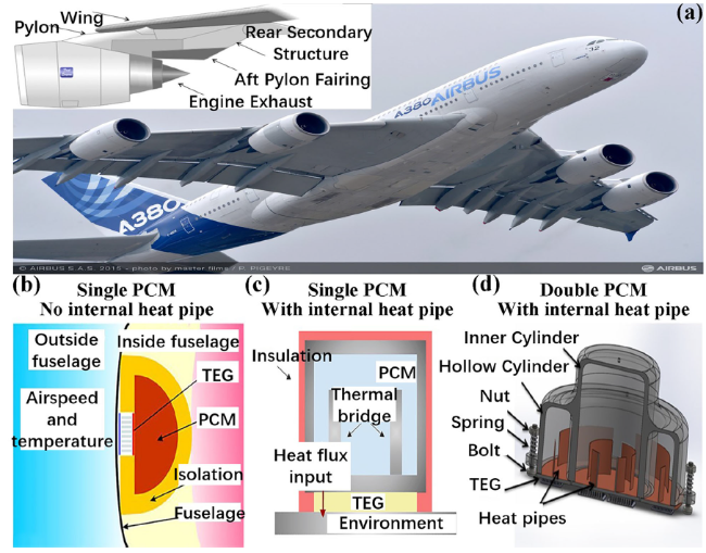
Fig. 4 Thermoelectric energy harvesting in aircraft: a Aft pylon fairing and a possible installation area where the TEG can be placed [74]; Schematic diagram and assembled device image of TEGs integrated with b single PCM (without internal heat pipe) [75], c single PCM (with internal heat pipe) [76,77], d double PCM (with internal heat pipe) [78] |
Aircraft-specific energy harvesting devices can be generally classified into three types according to the assembled configuration: TEG integrated with single PCM (without internal heat pipe), single PCM (with internal heat pipe), double PCM (with internal heat pipe). The following is a detailed description of these three types of prototypes. Following Elefsiniotis, Samson et al. developed an energy harvesting device consisting of a TEG attached to the inner part of the fuselage and a single PCM (water/ice) [75,79,80]. This design aims to provide sufficient electricity to sensor nodes through artificially enhancing the temperature difference between the bottom and the top surface of the TEG during take-off and landing. The experimental results demonstrate that the aircraft-specific energy harvesters have average energy output of 22.8 J under typical tests which are similar to short/mid-range flights. This energy is sufficient to power up a wireless sensor for more than 6 h according to extrapolations from regular energy requirement. It presents great potential in the aeronautical field and can reduce maintenance costs by up to €10 million over the lifetime of an aircraft. Based on previous studies, Kiziroglou and Elefsiniotis et al. continued to optimize the design of thermal storage unit. A single alternative PCM with internal heat pipe was encapsulated and integrated with the TEG. Addition of internal heat pipe enhances the heat flux from PCM to fuselage via the TEG, extending applicability to flight temperature profiles not necessarily traversing zero degrees [76,77]. Simultaneous measurements by Toh et al. revealed that the electrical energy harvested from an 80 min flight under peak conditions will be able to continuously supply 100 mW to the sensing system for 810 s [81]. In order to further improve the performance of energy harvesting device for aircraft by increasing its operational temperature range, on the basis of primary work, Elefsiniotis et al. reconstructed the thermal storage unit (with internal heat pipe) from a single cavity to two cavities for filling two different PCMs [78]. Experiments and simulations show that applicability of new design for this device can be significantly extended in key domains, such as effective working temperature, volume and energy output matching best to the requested flight duration. It demonstrates advantages of consistent behavior of the device in different temperature ranges. Meanwhile, they pointed out that improving the performance of aircraft-specific energy harvester while simultaneously decreasing the weight of PCM containment (i.e. decreasing weight-to-power ratio) will be the focuses for future activities. Future advancements include a redesign of the container geometry in order to minimize the surface area. Additionally, they also consider to make use of different container materials to encapsulate PCM, allowing TEG operate under higher working temperatures and further minimizing heat loss to the environment.
Different from above two applications, up to now, few efforts of employing TEG-PCM systems in ocean shipping and marine energy utilization have been performed. Figure 5 exhibits representative applications of thermoelectric energy retrieval of vessel, underwater glider and unmanned underwater vehicle (UUV) in ocean. The ocean shipping has a significant influence on climate change because there is a large amount of greenhouse gas emissions [87]. The utilization of waste heat onboard is mostly used for freshwater production and providing thermal energy (heating heavy fuel oil and accommodation places), but seldom for producing electrical energy. Heat sources on the marine vessels are mainly include main engine, lubrication oil cooler, power unit and incinerator [88]. The main engine and incinerator represent the principal source of waste heat on vessel, which is favorable for TEG-PCM system due to the availability of high temperature difference during sailing [82,89,90].
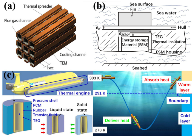
Fig. 5 Thermoelectric energy retrieval of vessel, underwater glider and unmanned underwater vehicle (UUV) in ocean: a Design of TEG with modular cross-section for installation in the flue from a waste incinerator onboard [82]; b Schematic diagram of a TEG-PCM system embedded in the hull of an underwater glider [84], and potential system arrangement inside hull; c Conceptual design of a double-layer structure oceanic thermal engine of UUV and schematic representation of ocean thermal energy conversion throughout its ascent and descent [85,86] |
The TEG-PCM system not only uses the high temperature difference of waste heat onboard for producing electricity, but also uses the low temperature difference reserve in ocean energy to further develop its power generation potential. Some researchers have figured out how to apply TEGs under weak ocean temperature differential conditions [91,92,93]. Inspired by these successful attempts, some scholars tried to miniaturize this technology and apply it to drive or power the unmanned underwater vehicle (UUV). Buckle et al. designed a novel TEG-PCM system utilizing the depth-related variation in oceanic temperature [83]. Intention of this design aims to offer a backup battery for autonomous underwater vehicle (AUV). One side of the TEG is contacted with a PCM-based thermal energy storage, the other side is indirectly contacted with the surrounding fluid. This has the potential to create a temperature difference providing the mission arena within a region with suitable oceanic temperatures. TEG-PCM systems for AUV can generate electricity from repeated dives with the primary purpose of extending mission range. This system can provide all the power needed for a modern AUV throughout its ascent and descent. It allows AUV for long-term measurements across a range of ocean depths and acquire a number of ocean properties such as salinity, fluorescence and temperature profile. Carneiro et al. presented a complete model of TEG-PCM system embedded in the hull of an underwater glider that designed for retrieval of energy from the ocean thermal gradient [84]. Several simulations are performed for determining the adequate design parameters, leading to generate sufficient energy for driving underwater glider. Using PCM as energy storage material (ESM) reduces the quantity of ESM required and presents highly advantageous over the use of sea water or stainless steel. Results obtained in this work reveal that 28.9 kg of PCM and 5000 series-connected TEGs allow the retrieval of the required 6 kJ of energy per each 1200 m diving cycle, sufficing to power a current commercial underwater glider. Wang et al. reviewed the application development of UUVs utilizing ocean thermal energy, as well as dedicated to an indication of future developments [85]. They found that PCM-based thermal energy storage remains the most promising way in ocean thermal UUVs. Moreover, applying TEG to UUVs for ocean thermal energy harvesting is more reliable and requires fewer intermediate conversion steps, thus reducing the probability of failure. If these two technologies can be integrated, although this method is only in the conceptual design stage, applying TEG-PCM system to UUVs based on ocean thermal energy harvesting has great promise form arine energy research and application.
3.1.2 PV-TEG-PCM
Photovoltaic (PV) technology, as one of the most common new energy conversion methods, can directly convert solar energy into high-quality electrical energy [94,95,96]. However, due to the band-gap limitation of the semiconductor materials used in PV cells, only a limited portion of the solar spectrum incident on PV cell can be converted into electricity [97]. The remaining absorbed solar energy has to be transformed into thermal energy and be wasted. Meanwhile, the temperature rise caused by unused solar heat also induces a negative impact on PV cell converting solar energy into electricity [98,99,100]. In view of TEGs capable of direct heat-electricity conversion, accordingly, the PV-TEG system combined by PV cell and TEG becomes a viable approach of realizing the utilization of full-spectrum solar energy. Compared to the pure PV system, a PV-TEG system with TEG can absorb residual solar heat from PV cell and convert it into electricity. Therefore, PV-TEG system may generate more electrical energy than pure PV system.
Numerous theoretical calculations, numerical simulations, and experimental measurements related to the PV-TEG systems have all verified the rationality and feasibility of the design. According to relevant literature reviews in recent 5 years, it can be seen that the PV-TEG systems have made considerable progresses and developments in the fields of building energy conservation and environmental protection, chemical industry and energy production etc. [101,102,103,104,105,106,107].
Nevertheless, since the solar irradiance within a day is varying, the temperature of a PV-TEG system fluctuates with the change of incident solar irradiance, which exerts a significant impact on the total efficiency. As shown in Fig. 6, the efficiency of PV cell decreases while that of TEG increases with temperature rise. There exists the highest efficiency when the temperature increases to a critical value, where it is the optimal working temperature for a PV-TEG system. Proceeding from this actuality, PV-TEG system integrated with PCM (PV-TEG-PCM) has been proposed, aiming to suppress the temperature fluctuation induced by fluctuant solar irradiance. PCM initially functions as heat sink to PV cell or TEG, and then operates as a heat source to the TEG when heat supply is insufficient. Applying appropriate PCM to PV-TEG system give a path to reconcile the requirements of PV and TEG for optimal working temperature at the same time. Similar to the classification of TEG-PCM system mentioned above, according to the relative position between PCM and TEG, PV-TEG-PCM system can be classified into two configuration types follow the arrangement of components from top to bottom: PV/TEG/PCM and PV/PCM/TEG. A series of studies focusing on this idea have attracted increasing attention in recent years, following representative studies presented in terms of above two classification types in turn. For PV/TEG/PCM, PCM integration primarily extracts thermal energy from TEG, making it more flexible. The dissipated heat stored within the PCM during daytime can guarantee the TEG to generate electricity at night. Meanwhile, the output power and efficiency of PV cell are also indirectly enhanced.
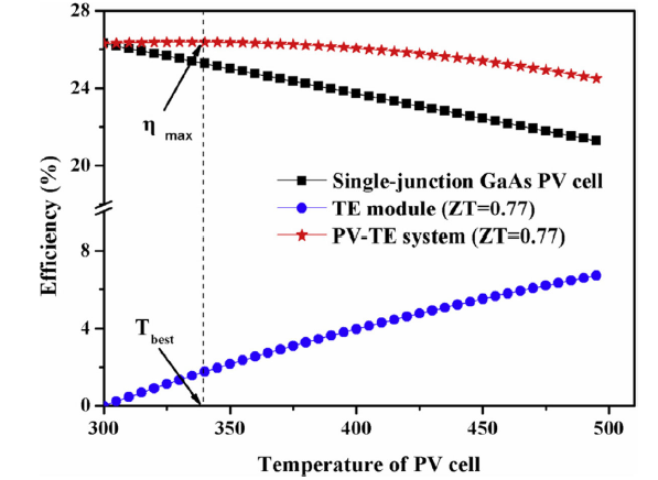
Fig. 6 Efficiency of PV-TEG system corresponding to different working temperatures [108] |
Darkwa et al. numerically and experimentally investigated the concept of an integrated PV/TEG/PCM system to enhance efficiency of PV cell [109]. Figure 7 presents physical arrangement and energy pathway of the PV/TEG/PCM system, the comparison of PV cell back temperature profiles among standard PV, PV-TEG and PV/TEG/PCM systems including temperature difference across hot and cold sides of the TEG for PV-TEG and PV/TEG/PCM system. It can be observed from Fig. 7(c) that the PV cell back temperature profile in PV/TEG/PCM system was significantly reduced during first 2 h as compared to the standard PV system. Consequently, it is noticeable that the temperature difference of TEG in PV/TEG/PCM system was remarkably enlarged during the phase transition of PCM, thereby producing high power. This enables PV/TEG/PCM to generate 6.7% and 4.5% more electricity than the standard PV system in the first 1 h and 2 h respectively. Simulation results also stressed the importance of high thermal conductivity for a PCM layer with suitable thickness and appropriate phase change temperature, which is beneficial to improve the electric performance of a PV-TEG system. Similar works were also carried out by Ko et al. and they perform simulations of the proposed system through using MATLAB R2020a [110]. Compared with the building-integrated photovoltaic system alone, the results show that the proposed PV-TEG system with selected PCMs exhibited a 1.09% annual increase in power generation and 0.91%. The effect of melting point of PCM on the efficiency and electrical performance of a PV/TEG/PCM system was studied by Motiei et al. [111]. In comparison to sole PV system and PV-TEG system, experimental results indicate that the efficiency of PV cell in PV/TEG/PCM system was obviously enhanced when applying PCM with proper melting point. The choice of appropriate PCM may cause the melting process to start earlier, thereby reducing the PV cell temperature and increasing temperature gradient across the TEG, which in turn yielded a better electrical performance for both PV cell and TEG. Recently, Rajaee et al. experimentally examined the effectiveness of simultaneous usage of diverse nanofluid and PCM as a combined cooling method on the performance of PV-TEG system [112]. The results reveal that PV-TEG system using 1% Co3O4/water nanofluid with improved PCM (paraffin wax/Alumina powder) would enhance its overall electrical efficiency by 12.28% compared to water cooling technique. This method shows that even if the electricity generated at night by use of the heat storage function of PCM is not considered, the overall electrical performance is expected to be enhanced by improving heat dissipation from the back of PV-TEG system.
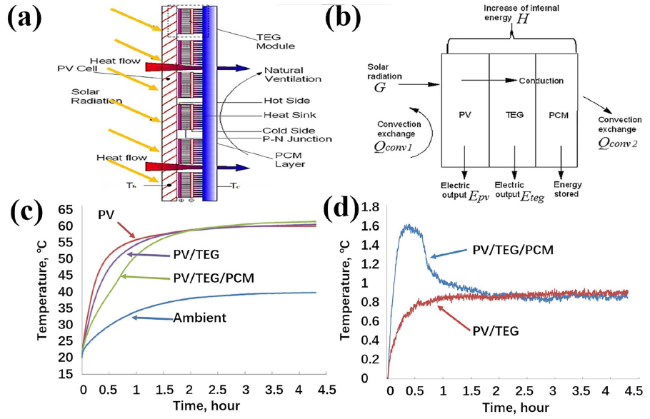
Fig. 7 a Physical arrangement and b energy pathway of the PV/TEG/PCM system; c PV cell back temperature profiles of standard PV, PV-TEG and PV/TEG/PCM system; d Temperature difference across hot and cold sides of the TEG for PV-TEG and PV/TEG/PCM system [109] |
For PV/PCM/TEG, the application of PCM have following three functions: reducing temperature rise of PV cell, stabilizing optimal working temperature of PV cell, and transferring solar heat to TEG. The main purpose is to ensure the PV cell to operate stably under optimal working condition, and TEG is used as an aid to increase the total power generation. By the way, PV/PCM/TEG system can be classified into separate-type and integrate-type according to the organization of components. A separate-type PV/PCM/TEG system to harvest solar energy from a wide spectral range for producing electricity has been proposed by Li et al. [113]. Solar spectrum splitter directs the short wavelength light to PV cell and the long wavelength light to PCM (i.e. heat storage) to generate electricity in PV cell and TEG respectively. Two closed-loop fluid circulations transfer the thermal energy from PCM to the hot side of TEG, and remove the excess heat from both cold side of TEG and back of PV cell. This design results in lower PV cell temperature and higher temperature difference within the TEG. Besides, a portion of electrical energy from the PV/PCM/TEG system can be used to refrigeration during off-peak times, then the stored cold energy could be utilized to regulate the PV cell and TEG temperatures during peak hours. Consequently, such a novel combined power generation system can provide 30% improvement in electrical output under reasonable working conditions. Similar works also have been carried out by Skovajsa et al. for improving the thermal comfortability in buildings interiors [114,115]. The combination of PV panels, solar thermal collectors, PCMs and TEGs offer a suitable possibility for optimizing cogeneration. The system can be used as a passive or active system for heating and cooling. In addition to the separate-type PV/PCM/TEG system, the integrate-type were also investigated by researchers over the past years. Naderi et al. designed a PV/PCM/TEG system for simulation analysis, aiming to improve the power generation and efficiency of PV cell [116]. The results show that the maximum output power and PV cell efficiency of PV/PCM/TEG system have been increased by nearly 100% and 1.38% respectively when compared to a solo PV system. This increase can be attributed to the PCM placed at back of PV cell. PCM absorbing solar heat results in the reduction in PV cell temperature, enhancing the efficiency.
Cui et al. introduced PCM into a PV-TEG system cooperated with Fresnel lens to construct a concentrated PV/PCM/TEG hybrid system [108,117]. The schematic illustrations of the structure and the energy flow of PV/PCM/TEG hybrid system is shown in Fig. 8. The purpose of applying PCM is to mitigate the temperature fluctuations of PV cell and TEG. Meanwhile, PCM conduces to the PV-TEG system operating under the optimal condition for the highest efficiency. The results indicate that the performance of the PV/PCM/TEG hybrid system is superior to single PV cell and PV-TEG system under the same circumstance. The theoretical and experimental works also reveal the feasibility of different types of PV cells used in such a hybrid system, which presents a promising potential on the full-spectrum utilization of solar energy. Based on the studies of Cui et al. mentioned above, Li et al. added a prismatic glass between Fresnel lens and PV cell to further increase the optical concentration ratio and to improve the electrical performance [118]. Experimental results indicate the average efficiency and output power of PV/PCM/TEG system were 6.16% and 1.496 W higher than that of PV-TEG system, respectively. They also verified the efficiency and output power increased with the rise of sunlight intensity and uniformity of light spot. Furtherly, Yin et al. investigated effects of thermal resistances on the performance of this system through optimizing TEG, PCM, thermal interface material (TIM) and cooling methods [119]. They concluded that employing the more efficient TEG, PCM and TIM with excellent thermal properties while loading high water-cooling rate of flow will prompt the concentrated PV-TEG system to generate more electricity. Recently, Zhang et al. established a thermodynamic model to study the energy matching mechanism of PV/PCM/TEG system [120]. They found that the relationship between the efficiency of system and the PV cell bandgap looks like a “reverse U” (rises first and falls later) with considering dynamic solar radiation. Impacts of optical concentration ratio and TE parameters are weak and the optimal PV bandgap of system is around 1.15 eV. It illustrates that the energy match does not depend on the solar radiation and the TE parameters. They also proved the melting point of PCM is important for determining whether it is worth to use and how much heat should be stored. This result may give a help to find the appropriate PV materials which is suitable for the PV-PCM-TEG system.
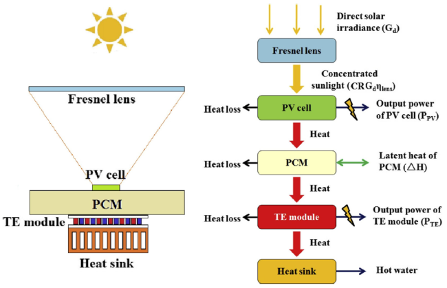
Fig. 8 Schematic illustrations of the structure and the energy flow of PV/PCM/TEG hybrid system [117] |
3.1.3 ST-TEG-PCM
Solar thermal (ST) cogeneration technology is a relatively mature energy collection and conversion method [121,122,123]. It can directly convert solar energy into thermal energy via absorber or collector, electrical energy can be also produced using a power block (TEG or vapour turbine) driven by concentrated heliostats [124,125,126]. For some special designs where the input heat flux (free or inexpensive) is widely available, the financial profitability of TEG has been significantly improved [127,128,129,130,131]. At this time, using thermal energy from sunlight as the heat source of TEG is a promising option, especially in the case of obtaining heat and electricity simultaneously in the same system or process. Although the sunlight intensity varies widely in different regions at different times, unlike PV cell, TEG has the ability to capture solar heat from a wide range of spectrum and convert it into electricity. The solar thermal thermoelectric generation (ST-TEG) system built on the basis of this consideration has attracted a lot of researches for a long time. A large number of theoretical calculations, numerical simulations and experimental tests related to the ST-TEG system have all validated the feasibility. According to correlative literature reviews in the past 5 years, it can be found that the ST-TEG system has acquired prominent achievements and progress in smart energy production, transmission and management [132,133,134,135,136].
However, due to the poor energy conversion efficiency of TEG and undesirable heat distribution, the further application and expansion of ST-TEG system is restricted. Thinking that the PCM can absorb or release latent heat in addition to sensible heat without an obvious temperature change while undergoing phase transition [137,138]. This property enables PCM to absorb and transfer more heat to the TEG for extended durations aids in day-night power generation. Thus, the TEG-PCM system enhances the temperature difference between two sides of TEG, thereby increasing the energy conversion potential. Therefore, it is a wise choice to integrate advantages of ST-TEG system and TEG-PCM system. ST-TEG-PCM system would promote the integration of solar thermal cogeneration. Similar to the classification principle of PV-TEG-PCM system, in terms of relative positions between TEG and PCM, ST-TEG-PCM system can be categorized into two configuration types following the sequence of receiving solar heat: ST/TEG/PCM and ST/PCM/TEG. During the past years, a series of investigations on the combination of solar thermal energy storage and heat-electricity conversion have been carried out, following representative studies are presented according to above two classification types in turn.
For ST/TEG/PCM, the application of PCM initially functions as heat sink cooperated with nature convection (during daytime), and then serves as heat source later (at night). This design is applicable to energy applications with short sunshine time and limited solar heat storage. Therefore, it is characterized by distributed installation, which is especially suitable for powering outdoor internet of things (IoT) wireless sensors, thereby making ST/TEG/PCM work more nimbly. A prototype work unit made of TEG and PCM for harvesting ambient renewable micro-energy during day and night were designed by Zhang, Agbossou et al. [139,140]. Figure 9 shows the sketch drawing and working mechanisms of the energy harvesting system, including the comparison of voltage generation and harvested energy in actual solar radiation between work units with and without PCM. PCM was encapsulated with thermal isolation materials and placed at back of TEG. It stored extra solar heat through TEG in the daytime while worked as heat source at night. Experimental results confirm the use of PCM accompanied with energy-harvesting duration extension. Moreover, voltage generation and harvested energy of the work unit with PCM are higher than the case of without PCM.
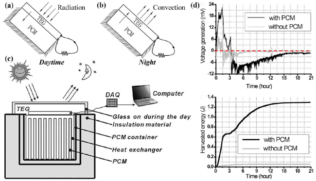
Fig. 9 Sketch drawings of the energy harvesting idea: a solar radiation on the TEG during the day and b PCM work as the heat source at night, c diagram of the prototype work unit in the outdoor experiment, d comparison of voltage generation and harvested energy in actual solar radiation between work units with and without PCM [139,140] |
Karthick, Jeyashree and Montero et al. also carried out similar studies and confirmed that ST/TEG/PCM is a reliable thermal design for reversible power generation with extended duration during all day [141,142,143]. This proposed prototype can be operated in space applications for micro power generation where solar radiation is the prime source of power. Thus, both of simulative and experimental investigation signify that the reversible operation of ST/TEG/PCM is favorable for day and night cycle operations for power generation. Tan et al. proposed a concentrated ST/TEG/PCM prototype utilizing two-phase closed thermosyphon as passive cooling method [144]. In order to enhance the heat transfer process, thermosyphon (wickless heat pipe) is implemented for transferring excess heat from the cold side of TEG to PCM for heat storage. The numerical simulation shows that solar concentration of 75 suns is able to create maximum temperature difference of 152 °C across the TEG and produce 9.5 W output power. Nakagawa et al. fabricated a high-efficiency sensor that mainly consists of TEG and storage unit filled with paraffin [145]. The sensor was installed on a manhole cover and bridge for powering wireless IoT monitoring system. Storage unit was arranged on the cold side of TEG. Solar heat absorbed from the manhole can be utilized by TEG to generate electricity in daytime. At night, PCM can continue to supply heat to TEG and thereby drive sensors detect early signs of overflows in sewer systems for a whole day. Furthermore, they refit this device by using alcohol solution as PCM. Experimental results clearly show the potential of the upgraded device effectively powering IoT sensor system of bridge for measuring river water levels [146]. Tahami et al. designed an innovative TEG-PCM energy harvesting system that utilizes thermal gradients between the asphalt pavement surface and the soil below and produces electricity [147]. Highway pavements exposed to the solar radiation could supply a large amount of heat to the TEGs. Incorporating a phase-changing heat sink further increases temperature differences across the TEG and enhances its performance. Field experimental results indicate that this system can generate an average power output of 29 mW per day. Hence, it is promising to powering road side wireless sensors monitoring road-health and near-field data communications. Muthu et al. redesigned the concentrator by use of parabolic dish for increasing the optical concentration ratio and improving electrical performance of ST/TEG/PCM [148]. Experimental results show that solar parabolic dish collector and PCM cooled heat sink are the driving potentials to produce electricity. When solar beam radiation is 1100 W/m2, the temperature of receiver plate at the hot side of TEG can reach up to 120 °C. At this time, a temperature difference of 80 °C is created on both sides of TEG and a maximum power of 1 W is obtained. Byon et al. developed a ST/TEG/PCM block as passive energy-harvesting brick which could be used in building envelopes [149]. It generates electricity by utilizing the solar heat accumulated at exterior wall surface. Power generation performance and thermal behaviors were evaluated in the laboratory. It is shown that the proposed energy-harvesting brick can generate an average power of 0.03 W in the extreme weather (0-50 °C), and the average amount of generated electrical energy is approximately 0.1 Wh. As a consequence, several ST/TEG/PCM blocks connected in series or parallel can be used as an independent power source for nearby sensors and controllers installed in smart buildings equipped with IoT wireless network. Besides, it also can be regenerated according to the natural temperature oscillation around the clock, which can operate continuously without additional energy.
For ST/PCM/TEG, it can complete small-scale and large-scale electrical energy production either in TEG or concentrated solar thermal power station, respectively. For small-scale electrical energy production, heat reservoir filling with PCM primarily extracts and store thermal energy from solar resource, and then transfers heat to TEGs for power generation. For large-scale electrical energy production, most of solar heat is transferred to the heat-exchange medium to produce high-temperature and high-pressure steam, which is used to drive the turbine for producing electricity in solar thermal power station, while the dissipated heat can be convert into electricity by TEGs at the same time. This design is appropriate for energy applications with long-time sunshine and abundant solar heat storage. Therefore, it is characterized by centralized installation, which is especially suitable for mass electricity production in the resource-rich area of solar irradiance. It further promotes the industrialization of ST-TEG-PCM system and improves the efficiency in the actual electrical energy production process. Kim et al. designed an innovative refraction-assisted solar thermoelectric generator (R-STEG) based on PCM (n-octadecane) [150]. The refractive index and transmittance change with phase transition of PCM, improving the refraction of sunlight and concentration of solar energy in the liquid PCM lens. This design facilitates double focusing the solar energy through optical and PCM lens. The maximum output power of the R-STEG is 60%, higher than that of the typical STEG at solar intensities of 1 kW/m2. Maduabuchi and Shittu et al. also validated the effect of PCM placed at the hot junction of STEG acting as thermal medium layer through numerical simulation [151,152]. The results demonstrate that PCM lens dramatically alleviates the adverse effect of transient and non-uniform solar radiation. These works present significant progress regarding to the electric characteristic and optical concentrator subsystem of PT/PCM/TEG. Demir et al. numerically modeled a separate-type hybrid system for electricity and hydrogen production and analyzed thermodynamically the performance [153]. The proposed system consists of a concentrated solar thermal power station, PCM (NaOH and Mg60Cu25Zn15) heat storage unit, TEG with heat exchanger, a multi-stage flash distillation (MFD) and a proton exchange membrane (PEM) electrolyzer. The overall energy production process undergoes three steps. Firstly, the PCM heat storage unit receives and reserves solar heat reflected by heliostats, and then utilizes heat for preparation of pressurized steam to drive turbines for producing electricity. Secondly, unutilized waste heat from turbine can be restored by PCM and converted by TEG into electrical energy. Finally, the rest heat was utilized by MFD for seawater desalination while the PEM electrolyzer produce H2 and O2 from the distilled water. The overall energy and exergy efficiencies of hybrid system were calculated as 42.5% and 40.5%, respectively. Besides, this system has 1210 tons/day of fresh water, 129.9 kg/day of hydrogen and 267.9 kW of maximum electric power production capacity.
Oshman following Rea’s design, constructed and experimentally investigated the concentrated ST/PCM/TEG power station, which uses a thermosyphon-based thermal valve with sodium working fluid to rapidly extract heat from sunlight reflected from heliostats [154,155]. Figure 10 shows the schematic diagram, internal structure sectional view and working mechanism of the proposed ST/PCM/TEG power station with dispatchable heat storage and thermal valve. The thermal valve used in this work is based on a gravity-assisted thermosyphon. Thermal energy can be stored in PCM (molten salts or eutectic alloy) to drive Stirling engine and utilizing heat-electricity conversion of TEG for producing dispatchable electrical power. Numerical calculation and experimental results demonstrate that the heliostat fields of this innovative design are 1000× smaller than conventional requirement through using passive thermal transport mechanisms including heat pipe and gravity-assisted thermosyphon. Meanwhile, the cascaded TEG consisting of Skutterudite and Bi2Te3 is able to convert heat with temperature gradients of < 6 °C into electricity, thus further enhancing the power generation. This simple and effective technology shows a strong impact on the feasibility, scalability, and dispatchability of ST/PCM/TEG power station [156].
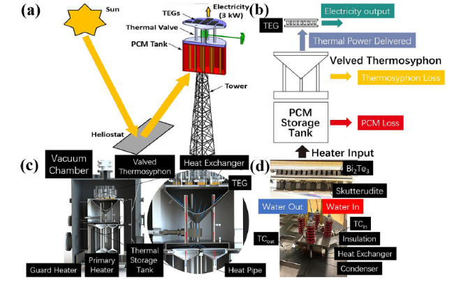
Fig. 10 a Schematic diagram and b working mechanism of the proposed ST/PCM/TEG power station with dispatchable heat storage and thermal valve, c internal structure sectional view of the thermosyphon-based thermal valve used for controlling high-temperature heat flow from PCM to TEG, d the cascaded TEG consisting of two types of TEGs: Skutterudite TEG on the hot side and Bi2Te3 TEG on the cold side (TIM is used for enhancing the heat transfer between two TEGs) [154,155] |
3.2 TEC-PCM
TEC-PCM systems show great potential in terms of temperature control, two most important practical applications of TEC-PCM systems are air conditioning and battery thermal management. Following details are a summary of design ideas and relevant applications.
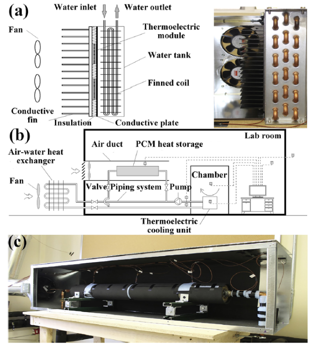
The 2D heat transfer model of a TEC with PCM-based heat sink (attached to cold- or hot- side of TEC) has been developed and numerically studied by Selvam following Manikandan et al. [46,51,157]. The schematic representation of TEC integrated with PCM-based heat sink is shown in Fig. 11. Under varying electric pulse operation as compared to the case of TEC without PCM, the results show that TEC with PCM not only significantly increases the COP, but also achieves remarkable decrease in cold-side temperature of TEC or maintains relatively low hot-side temperature of TEC constant. They also found that the convective heat transfer coefficient, geometric parameters of heat sink, PCM type and filling volume in heat sink, cooling load condition and the shape of electric pulse are predominant with thermal performance of this technique. Zhao and Tan developed a prototype of TEC-PCM system used as air-conditioner for buildings [158,159]. Figure 12 presents the schematic diagram and photograph of TEC-PCM system. The PCM functions as cooling source and carries cooling load during cooling operation in this work. Thermal efficiency of TEC is enhanced because PCM stores heat and thereby reducing the hot side temperature of TEC at runtime. Experimental test in a lab-scale chamber has saved 35.3% electrical energy and obtained 7 °C temperature difference between indoor and outdoor environments. It realizes a joint increase in both the average COP and the maximum cooling capacity. They also pointed out that the cooling load and local weather condition are required to be considered for meeting with specific cooling application.
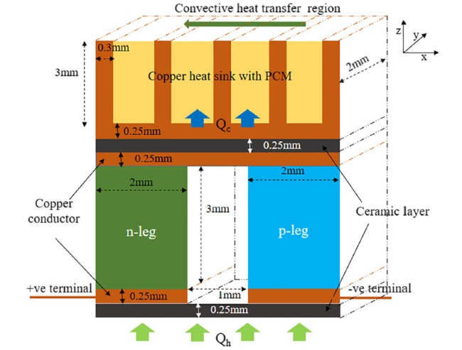
Fig. 11 Schematic representation of TEC integrated with PCM-based heat sink [46] |
Siddique et al. regarded TEC-PCM as the most promising active cooling technology in battery thermal management solution (BTMS) according to literature review [23]. Two representative cases below illustrate the general idea and application of the TEC-PCM system for BTMS. A BTMS of standby battery for outdoor base station based on the TEC and PCM was report by Song et al. [160]. The schematic diagram of the standby battery pack with TEC and PCM for outdoor base station is shown in Fig. 13. This strategy can cool/heat the battery module and keep its temperature in optimal range, while withstand temperature fluctuations induced by ambient surrounding changes or discharge-charge process. It shows the potential of TEC-PCM system working stably during continuous cooling/heating preservation thermal cycle. Similarly, in view of the temperature changes of lithium ion battery under different discharge rates. The heat transfer of PCM was improved by Zhang et al. through adding expanded graphite (EG) to paraffin, and combined it with TEC for power battery pack heat dissipation [161]. Experimental results show that the surface temperature of battery can be kept within a reasonable range when discharging at high rate. It not only improves the temperature uniformity of battery, but also consumes fewer electricity to obtain better cooling effect.
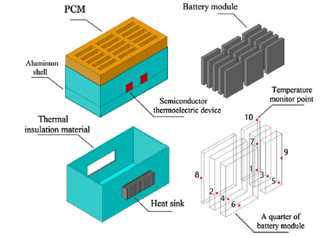
Fig. 13 Schematic diagram of the standby battery pack with TEC and PCM for outdoor base station [160] |
From research works summarized above, it is not difficult to see that, in terms of thermal management, TEC-PCM system provides remarkably better COP values and cooling power compared to the conventional TEC system. It would promote TEC to have a wide range of applications from aerospace, military to biology and medicine.
4 Design optimization
In recent years, TE-PCM systems have achieved further improvements through design optimization. One hand is component optimization, which mainly includes improving thermal capability of PCM and promoting performance of TE devices. On the other hand, the potential of components can be fully exploited through structural optimization and reasonable configuration. Up to now, researches on the design optimization of TEC-PCM systems are rare and here we focus on the literature reports of TEG-PCM systems using improved PCM.
4.1 PCM
The priority of thermal management in TE-PCM systems is to improve thermal capability of PCM. Reasonable deployment of the PCM and choosing the PCM with appropriate thermophysical properties are essential to the temperature control. According to this scientific thinking, researchers have made efforts to apply improved PCMs into TEG-PCM systems for enhancing performance in past decade. Zhu et al. demonstrated that the total electrical energy of TEGs could be largely enhanced through multi-parameter optimization design of PCMs [162]. The results validated that the maximum output power could be obtained when the phase change temperature of PCM is approximately equal to the average operating temperature of TEG. Mizuno et al. developed a thermal buffer device (TBD) to stabilize the heat input to TEG and protect it from large temperature fluctuations [163]. These heat buffers are a combination of two alloy PCMs with large enthalpies of fusion and the two alloy PCMs are placed in series. Adding PCM on the basis of PCM/TE expands the operating temperature range of TEG beyond 573 K with no notable damage and further enable stable electric power supply. Tu et al. presents a new TEG system applied in extreme large temperature variation by introducing paraffin/EG(expanded-graphite) composites [164]. Pure paraffin was distributed into 5 to 10 wt% of EG to solve liquid leakage and incidentally increase the thermal conductivity of PCM. Both of numerical simulation and experimental evidence demonstrate that the TEG system using paraffin/5wt%EG is perfect for upgrading output performance. The use of paraffin/5wt%EG not only balances the heat storage capacity and the heat transfer rate, but also makes the TEG system perform a 32.32% total output energy increase than that of common one using pure paraffin. Similarly, Liu et al. prepared a composite PCM comprising paraffin and multi-walled carbon nanotubes (CNTs) and embedded it into the hot side of a TEG [165]. In addition, the effect of the geometrical structure of PCM on the output performance of TEG was also investigated. The results show that paraffin/1.5wt%CNTs improves thermal conductivity of PCM while maintains latent heat with few decreases. The use of paraffin/1.5wt%CNTs promotes the maximum electrical energy generated by TEG to increase by about 34.9% compared to that without PCM. Besides, it also proves to be feasible in enhancing electricity production through appropriately increasing the height of embedded PCM. Cottrill et al. exploited PCM with ultra-high thermal diffusivity in a TEG system for energy harvesting over large ranges of thermal frequencies [166]. Thermal diffusivity of PCM was maximized by impregnating copper and nickel foams with conformal, chemical-vapor-deposited graphene and octadecane. Theoretical analysis and experimental measurements demonstrate that the harvestable power is proportional to the thermal diffusivity of the dominant thermal mass. Yu et al. prepared a composite PCM with novel structure for heat transfer enhancement and used it to improve the power generation of a TEG in a fluctuating thermal environment [167]. Figure 14 illustrates the structure and heat conduction mechanism of the composite PCM sample, including the schematic diagram and open circuit voltage variations of the TEG system with composite PCM. Rolled graphene film (Gflim) as thermal conductive fillers was embedded into graphene foam (Gfoam) through the ice-templated method to form material skeleton. This composite structure increases the thermal conductivity of pure paraffin wax (PW) by nearly 44 times with a very small mass cost. The results indicate that increasing thermal conductivity of PCM helps it to better play a buffering effect, and significantly reduce the voltage fluctuation of TEG.
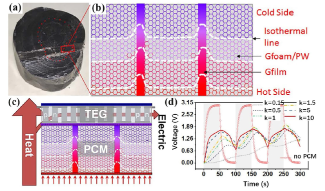
Fig. 14 Gfilm/Gfoam/PW: a structure of composite PCM sample, b heat conduction mechanism, c schematic diagram of TEG system with composite PCM, d open circuit voltage variations of the TEG with PCMs that have different thermal conductivities in the fluctuating thermal environment [167] |
Jiang et al. proposed to assemble graphene in a polyethyleneglycol matrix composite (G-PEG) and supply heat for a TEG [168]. 3D interconnected netlike architecture of G-PEG not only affords more heat transfer pathways, but also acts as highly thermally conductive reservoirs to enhance thermal energy collection, storage and release. I-t curves of TEG coated with G-PEG reveal that increasing the PEG content and the thickness of G-PEG will possess longer steady-state current output time. Yang et al. introduced a very low content of graphene nanoplatelets (GNP) into poly ethylene glycol (PEG)/boron nitride (BN). Figure 15 shows the thermally conductive pathway of composite PCM, involving the experimental setup of a TEG with composite PCM for solar-thermal-electric energy conversion and its I-t and U-t curves under simulant sunlight radiation. The results indicate that great improvement in thermal conductivity and photoabsorption ability of composite PCM has been obtained through a facile solution blending process [169]. Besides, they also realized solar-thermal-electric energy conversion through assembling the TEG with PEG/BN/GNP composite PCMs under simulant sunlight radiation.
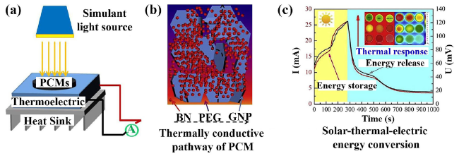
Fig. 15 a Experimental setup of a TEG with composite PCM for solar-thermal-electric energy conversion, b thermally conductive pathway of PEG/BN/GNP composite PCM, c I-t and U-t curves of the TEG with composite PCMs under simulant sunlight radiation (at 400 mW/cm2) on/off [169] |
Yu et al. prepared a novel PCM macrocapsule for heat storage by means of a cast molding method, which consists of octadecanol as the core and the silicone elastomer for encapsulation [170]. Figure 16 shows the image of PCM macrocapsule and its heat charging and discharging used for a TEG, including temperature profiles of PCM macrocapsule and two sides of TEG, and the output voltage, electric current and output power, temperature difference variations on both sides of TEG. It can be dynamically and repeatedly remodeled as needed to a complicated shape with large-scale deformation. Thus, the stress mismatch that caused by volumetric changes of PCM during phase transition was effectively eliminated, through the self-adaptative deformation of the coated flexible shell. In addition, they also applied the prepared PCM macrocapsules as thermal management for flexible electronic devices and heat storage for thermoelectric energy harvesting. This study demonstrates good development foreground of elastic PCM capsule applications in energy storage and thermal control engineering.
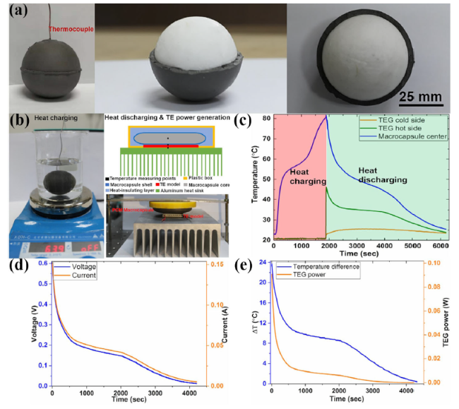
Fig. 16 a Optical photos of the PCM macrocapsule that consists of octadecanol core and silicone elastomer shell, b heat charging and discharging of the PCM macrocapsule used for TEG, c temperature profiles of PCM macrocapsule and two sides of TEG, d output voltage, electric current and e output power, temperature difference on both sides of TEG versus time [170] |
Yu et al. introduced a reusable energy harvesting system consisting of a TEG and two different composite PCMs. The system can recover discarded heat by utilizing temperature variation from surroundings [47]. Figure 17 shows the schematic illustration of the thermoelectric energy harvesting system with two PCMs, involving temperature profiles of PCMs and electric current variations of the TEG. A 3D porous graphene aerogel was embedded in poly ethylene glycol (PEG) and 1-tetradecanol (1-TD), and the shape stability and thermal conductivity of PCM composite was enhanced without significant loss of latent heat. The maximum value of electric current reaches 10 mA during heating and cooling processes and the harvesting time region has been maintained at 1900 s and 850 s. The obtained electrical energy is enough to drive a red LED light up. Niu et al. also conducted similar works, a thermo- and sunlight-driven energy conversion and storage material was fabricated by the combination of organic PCM with carbon nanofiber aerogels (CNFAs) [171]. Two different PCM/CNFA composites (stearic acid/CNFA (PCM-SA) and 1-tetradecanol/CNFA (PCM-1-TD)) were used and assembled with the TEG to develop an energy harvesting system. Dissipated heat and solar energy could be converted by the system into electricity in an environment with spatially uniform temperature. This energy harvesting device generates a maximum power density of 1.20 W/m2 in the sunlight-driven thermoelectric conversion process. Recently, Madruga theoretically studied the cold side of a TEG joined to a PCM improved with metallic foam. The device enhanced micro-energy harvesting to transform ambient thermal fluctuations into electricity [172]. The porosity of metallic foam accelerates the heat transfer and permits higher volumes of PCM to be effective in harvesting more energy from the surroundings. When using a modified PCM (metal foam porosity is 0.95), simulation results demonstrated that TEG could generate twenty times more electrical energy than the usage of only PCM under low solar thermal gradient conditions.
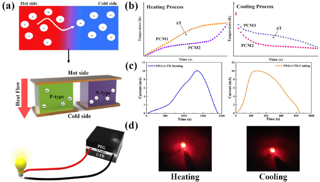
Fig. 17 a Schematic illustration of the thermoelectric energy harvesting system with two PCMs involved PEG and 1-TD embedded with porous graphene aerogel during heating and cooling process: b temperature profiles of PCMs, c electric current variations of TEG, d red LED light turned on using the harvested electrical energy [47] |
4.2 TE device
The importance of using TE devices with better performance and applicability for improving power generation of TE-PCM system is only next to optimizing the thermal properties of PCMs. With the acceleration of R&D in the thermoelectric field, TEC for refrigeration is undoubtedly successful and mature in commercial promotion and practical application, while TEG for power generation is still limited by low conversion efficiency. The survey of application actuality of TE devices in TE-PCM systems shows that thermoelectric materials currently used for manufacture TE devices are still dominated by bismuth telluride alloys, which has been commercially available for long time [18]. However, the limited efficiency and relatively high cost remain the main barriers against the industrialization of TE devices based on commercial thermoelectric materials. Therefore, looking for thermoelectric materials with excellent performance, high quality and low price, reducing material synthesis and device manufacturing costs (including reducing toxicity and pollution), and introducing new assembly technologies are important rules for improving the performance of TE device [17,173]. The output power of a TEG can be increased by performing segmental reform in different operating temperature zones, i.e. combining different semiconductor materials such as lead telluride, Skutterudite, etc. as p-type or n-type thermoelectric materials [174,175,176,177]. Some studies have confirmed that the overall performance of TE device can be also improved by optimizing geometrical and structural design [178,179,180].
4.3 Structure
Another key factor to increase electricity production of TEG-PCM systems is creative structure design. The implementation of adequately collecting and transferring heat is along with efficient use of thermal energy through optimizing the component configuration of TE-PCM systems. At the same time, the compatibility of various energy collection and conversion systems have also been improved. In recent years, a number of representative innovative TE-PCM system designs have been developed.
Yoon et al. reported an impact-triggered TEG that used latent heat liberated from the crystallization of supersaturated sodium acetate trihydrate (SSAT) [181]. Figure 18 presents the basic structure, exploded view and application example of the impact triggered TEG. SSAT was encapsulated in a polydimethylsiloxane (PDMS) chamber and capped with a steel cap. The device will activate once an external impact is applied to the steel cap. The heat released from exothermic crystallization process of SSAT creates a thermal gradient across the TEG which in turn generates electrical energy. Simple and portable design, good power output and reusability are attractive features of this device. A typical application of this device is indicated when and where the fragile package delivery is dropped through sending radio signals during shipment.
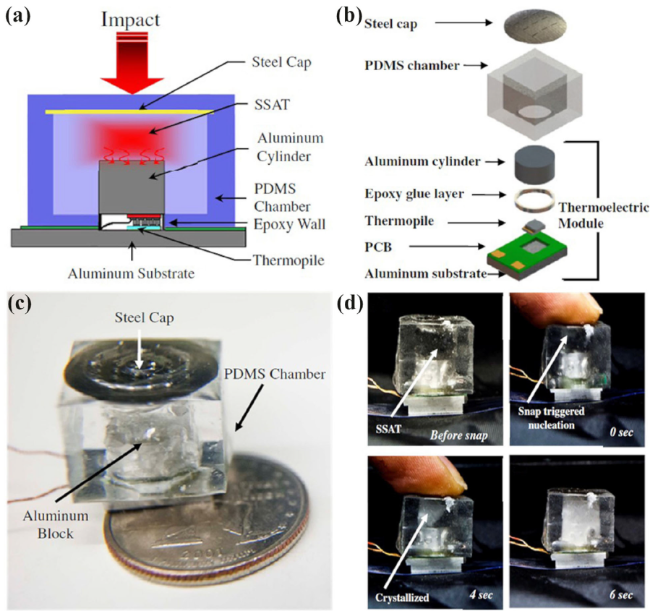
Fig. 18 Impact triggered TEG: a basic structure, b exploded view of the device showing various components, c photograph of the device with PDMS chamber, d snapshots of sodium acetate trihydrate crystallization process after impact trigger [181] |
A prototype using thermosyphon with phase change as heat exchanger were built by Araiz et al. and the thermosyphon was placed on the cold side of TEG [182]. The prototype of the TEG system using thermosyphon with phase change as heat exchanger is shown in Fig. 19. Thermosyphon effect makes the fluid flow in the exchanger only need the evaporator to be below the condenser. This design takes advantage of density differences and gravity to allow the fluid drain back once it has been condensed. The power generation of the TEG increases by 36% compared to that obtained with finned dissipators under forced convection because it does not require extra electric consumption to feed fan or pump working.
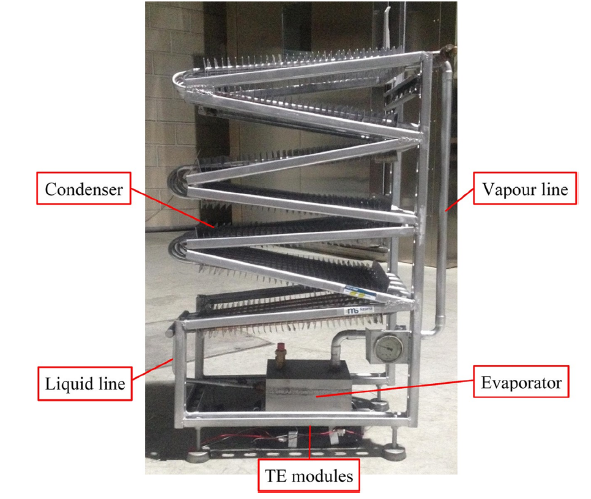
Fig. 19 Prototype of a TEG system using thermosyphon with phase change as heat exchanger [182] |
Atalay et al. developed a TEG system with two-phase thermosyphon heat pipes and nanofluids [183]. Figure 20 shows the physical structure of the TEG system with two-phase thermosyphon heat pipes and nanofluids. The cold side of TEG is cooled by aluminum heat sink. The hot side of TEG is heated by driving the vapor generated from nanofluids (MgO nanoparticle-water suspension). Nanofluids in the two-phase thermosyphon heat pipe create a reciprocating cycle of evaporation and condensation under gravity and concentrated solar radiation. Temperature difference is obtained between two sides of the TEG and electricity is produced. Experimental results give the necessity of nanofluids used for working medium and show that it is possible to acquire maximum power by optimize parameters such as the tilt angle of heat pipes, working fluids, cooling process, etc.
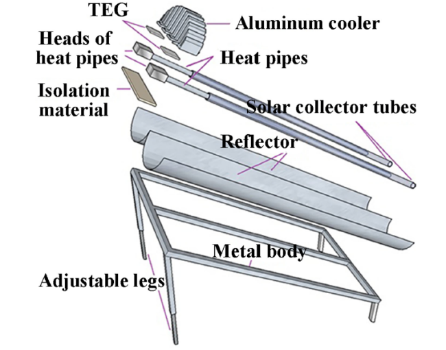
Fig. 20 Physical structure of a TEG system with two-phase thermosyphon heat pipes and nanofluids [183] |
A novel prototype of two-stage TEG system to improve power generation performance was proposed Atouei et al. [184]. The schematic diagram and side view of two-stage TEG system are shown in Fig. 21. PCMs were used as heat sink and heat source in the first stage and second stage, respectively. The function of the two-stage TEG system with mutually perpendicular structure likes a combination of TE/PCM and PCM/TE. The results show that the two-stage TEG system generates 27% more electrical energy than one-stage TEG system in the same test condition. Also, this new design makes the time duration of producing same quality of electricity extend by nearly 4 times when the heat source is cut off. Similar works were also conducted by Sui et al., they proposed a two-stage TEG system integrated with PCM and examined the effects of different heat sink configurations on the heat generated [185]. The results show that the properties of different PCMs significantly influenced the duration of voltage in each stage.
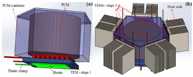
Fig. 21 Schematic diagram of two-stage TEG system: a TEG and heat source in stage 1, b TEGs and heat sinks in stage 2 [184] |
Kim et al. demonstrated a prototype of triboelectric-thermoelectric hybrid nanogenerator with PCM for harvesting both of kinetic friction energy and the thermal energy that arises from its inherent sliding motions [186]. Figure 22 presents the detailed illustration of structure and working mechanism of hybrid nanogenerator with PCM. The triboelectric part consists of a polytetrafluoroethylene (PTFE) film with nanostructures and a movable aluminum panel. The thermoelectric part is attached to the bottom of PTFE film by an adhesive PCM layer. The performance of device was significantly improved because PCM layer could continue to generate electrical energy from environmental temperature changes when there was no motion. This hybrid nanogenerator is specially devote to embedded into the rotating parts of automobiles or other machinery. It is also particularly suitable for application range of touch sensors.
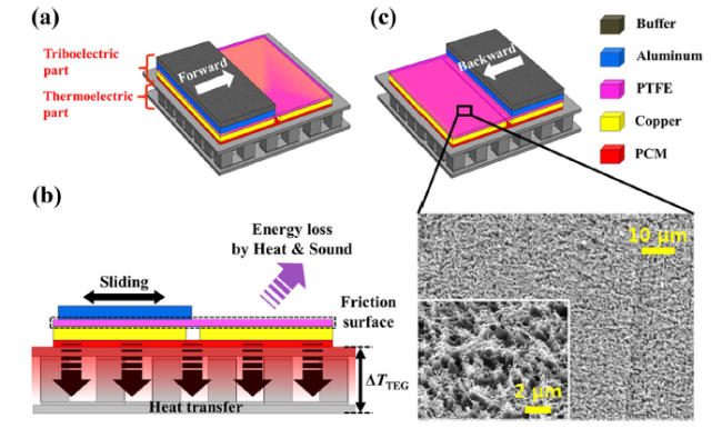
Fig. 22 a Proposed hybrid nanogenerator, b detailed illustration of the working mechanism of the hybrid nanogenerator, c FESEM image of the nanostructured PTFE surface [186] |
Shi et al. presented a novel self-powered wireless temperature sensor (SPWTS) that consists of a TEG and PCM-integrated heat sink [187,188]. Figure 23 illustrates the cross-sectional schematic diagram and photograph of the SPWTS that consists of a TEG and PCM-integrated heat sink, involving three arrangement types of heatsink and the comparison of voltage profile in TEG using heat sink with integration of water or paraffin. Introducing paraffin to serve as a temperature stabilizer, the performance of temperature probe is improved and the accuracy is further promoted. Moreover, heat sink with 2D plane structure evolving to 3D thermal extensional structure is designed to extend the thermal contact interface, while reduce the requirement of thermal contact area of compact sensor. Additionally, the TEG using heat sink with integration of paraffin makes the reverse output voltage keep more sustained than that using water cooling. This sensor can autonomously perform temperature measurement under positive temperature fluctuation situations and transmitting wireless data in time. It is expected to detect fire before it develops to flashover state and the maximum detection distance grows with the growth of burning rate.
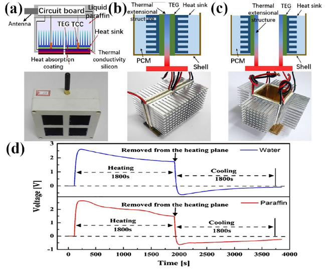
Fig. 23 Cross-sectional schematic diagram and photograph of a SPWTS that consists of TEG and PCM-integrated heat sink, three arrangement types of heatsink with a 2D plane parallel structure, b 3D filling thermal extensional structure c 3D hollow thermal extensional structure; d comparison of voltage profile in TEG using heat sink with integration of water or paraffin [187,188] |
Based on previous research works, Yu et al. further demonstrated a multiple energy harvesting system which is composed of two pairs of PEG and 1-TD PCM couples (the position layout of PCM couples are opposite) and two TEGs [47,189]. The schematic illustrations of the multiple energy harvesting system composed of two pairs of PEGs and 1-TD PCMs couples and two TEGs are shown in Fig. 24, including electric current profiles during heating and cooling processes. During melting or crystallization processes of the PCM, electric energy was harvested for 2200 s and 850 s at first stage and then for 2700 s and 1500 s at second stage. The TEGs produce additional electric current induced by the reversed temperature difference created through employing two pairs of PCM couples. Compared with TEG employing only one pair of PCMs, that using two pairs of PCM couples generates a relatively high efficiency and a large amount of electricity during phase transitions because of temperature reversal.
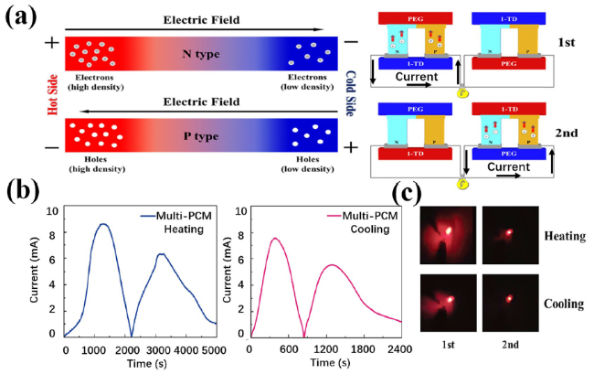
Fig. 24 a Schematic illustrations of the multiple energy harvesting system composed of two pairs of PEG and 1-TD PCM couples and two TEGs, b electric current profiles during heating and cooling processes, c images of red LED bulb lit by using the harvested electric energy [189] |
Lee et al. proposed a high-performance flexible PCM-based heatsink and integrated it with a flexible TEG [190]. The schematic diagram, component photographs and working mechanism of a flexible TEG with PCM-based heatsink are shown in Fig. 25, including the comparison of open-circuit voltage between the flexible TEG using PCM-based heatsink and using metal heatsink. Good flexibility of novel heatsink was realized with an elastomer that filled the space between PCM blocks. The new-design of heatsink is not only small in size and light in weight, but also holds sufficient temperature difference of TEG for constant during a relatively long period of time. This device can be attached to an arbitrarily shaped surface on the human body and the generated power was maintained at around 20 μW/cm2 for 33 min. It is expected to contribute to the commercialization of self-powered wearable devices such as an electrocardiograph or a pulse oximeter.
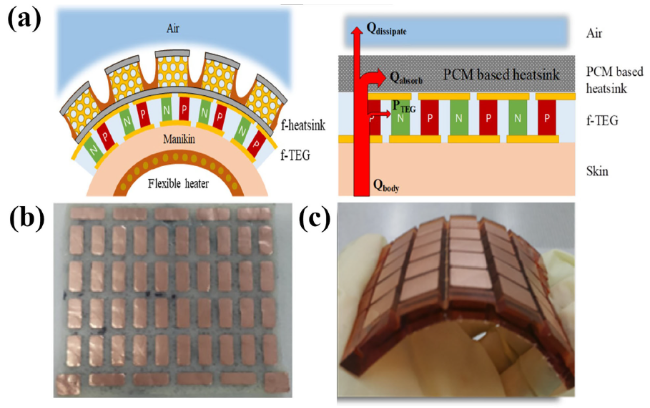
Fig. 25 a Schematic diagram and working mechanism of a flexible TEG with PCM-based heatsink, b photograph of flexible TEG, c structure design of PCM-based flexible heatsink [190] |
5 Future outlook
The low ZT and COP of TE device, the non-ideal thermophysical properties of PCM, and the imperfect structural design are negative factors restricting the performance improvement of TE-PCM systems. If TE devices with higher conversion efficiency, PCMs with superior thermal performance and systematic structure with optimized design can be used in the future, it is positive to further reduce economic costs and improve performance. TE-PCM systems will have a vast prospect of being applied in a wide range. In addition to above three core factors, there are other plenty of approaches that are worth adopting to further improve the overall performance of TE-PCM systems.
From the perspective of optimizing heat transfer within the systems, there are numerous innovations in this domain are needed to further investigate. For the hot side of TE-PCM systems, the capturing, collection and storage of heat are very important. Therefore, it is urgent to apply new thermal technologies to improve the current low thermal efficiency. Such as introducing novel solar concentrator and absorber [125,191,192,193,194], integration with advanced thermophotovoltaic (TPV) technology [195,196,197], using heat pipes and photothermal nanofluids [198,199,200,201] etc. are all promising research directions to improve heat collection and light-to-heat conversion efficiency. For the cold side of TE-PCM systems, the timeliness and effectiveness of heat transfer are always necessary to be request. Therefore, heat transfer media and heat sink with excellent cooling performance are desired to improve heat exchange effect. Such as using metal-based nanofluids [202,203,204] and microchannel heat sink [205,206] and optimizing heat fins arrangement design [207] are all effective solutions to improve heat transfer efficiency. In addition, it is also very important to improve the matching and coordination among components of TE-PCM systems by optimizing interfacial thermal conduction and layout [208]. Recently, some preliminary progresses have been made in related studies [209,210].
6 Conclusion
Herein, this paper summarized an updated overview of latest developments related to the utilization of TE-PCM systems as power generation and temperature regulation option combined with various structure design and processes. Following kernels have been drawn from this review:
·TE-PCM systems acting as an alternative hybrid energy technology can provide both clean electricity and heat/cold energy at the same time. Their application presents important development potential in terms of compatibility with conventional energy technologies, temperature control, energy production and storage.
·The optimization requirements of TE-PCM systems are mainly focused on enhancing the capturing and collection of heat energy and optimizing thermal conduction. For the former, it is necessary to design innovative heat absorber and collector, and develop new heat absorption and energy storage materials. For the latter, it is urgent to apply superior heat exchange media and heat sink with excellent heat transfer performance.
·Improving the assembly processes of TE devices while reducing material preparation and manufacturing costs are core elements to enhance the performance of TE-PCM systems. It is also the prerequisite for determining whether the TE-PCM systems can be widely promoted.
·It is recommended to take structural design as a breakthrough to further expand the application scope of TE-PCM systems through improving compatibility with other energy devices or systems.
In general, technological breakthroughs and further expansion of industrial scale may enable TE-PCM systems to provide low cost, modular, dispatchable electricity for microgrids or larger scale energy production and storage. To turn TE-PCM systems into in-depth practical application, more research works are worthy to be explored.
Abbreviations
TE: Thermoelectric; PCM: Phase change material; TEG: Thermoelectric generator; TEC: Thermoelectric cooler; PE: Pentaerythritol; TWC: Three-way catalytic converterv UUV: Unmanned underwater vehicle; AUV: Autonomous underwater vehicle; ESM: Energy storage material; PV: Photovoltaic; TIM: Thermal interface material; ST: Solar thermal cogeneration technology; MFD: Multi-stage flash distillation; PEM: Proton exchange membrane; BTMS: Battery thermal management solution; EG: Expanded graphite; CNT: Carbon nanotube; Gflim: Graphene film; Gfoam: Graphene foam; PW: Paraffin wax; PEG: Poly ethylene glycol; GNP: Graphene nanoplatelet; BN: Boron nitride; 1-TD: 1-Tetradecanol; CNFA: Carbon nanofiber aerogel; SA: Stearic acid; PDMS: Polydimethylsiloxane; PTFE: Polytetrafluoroethylene; SPWTS: Self-powered wireless temperature sensor; TPV: Thermophotovoltaic; S : Seebeck coefficient, V/K; σ : Electrical conductivity, Ω?m; κ : Thermal conductivity, W/m?K; κ e : Electronic thermal conductivity, W/m?K; κ l : Lattice thermal conductivity, W/m?K; T : Temperature, K; T m : Melting point of PCM, K; ZT : Figure of merit; η : Efficiency, %; COP : Coefficient of performance; ρ : Density of TE device, g/cm3; C p : Specific heat capacity of TE device, J/g?K; q : Heat flux of Fourier heat conduction and Peltier heat, W; Q : Internal heat generation of TE device, W; J : Electric current density, A/m2; ρ c : Charge density, C/m2; E : Electric field, V/m; P : Peltier coefficient, W/A; V : Voltage, V; ρ PCM : Density of PCM, g/cm3; C p,PCM : Specific heat capacity of PCM, J/g?K; u : Velocity of PCM, m/s; κ PCM : Thermal conductivity of PCM, W/m?K; L f : Latent heat capacity of PCM, J/g; α : Change of mass fraction of PCM, %; θ : Smooth phase transition function of PCM, %; Q in : Energy input, W; W : Electrical energy or cold energy converted from TE device, W; h : Hot side; c : Cold side; avg : Average; solid : Solid state of PCM; liquid : Liquid state of PCM
Greek symbols
S: Seebeck coefficient, V/K; σ: Electrical conductivity, Ω∙m; κ: Thermal conductivity, W/m∙K; κe: Electronic thermal conductivity, W/m∙K; κl: Lattice thermal conductivity, W/m∙K; T: Temperature, K; Tm: Melting point of PCM, K; ZT: Figure of merit; η: Efficiency, %; COP: Coefficient of performance; ρ: Density of TE device, g/cm3; Cp: Specific heat capacity of TE device, J/g∙K; q: Heat flux of Fourier heat conduction and Peltier heat, W; Q: Internal heat generation of TE device, W; J: Electric current density, A/m2; ρc: Charge density, C/m2; E: Electric field, V/m; P: Peltier coefficient, W/A; V: Voltage, V; ρPCM: Density of PCM, g/cm3; Cp,PCM: Specific heat capacity of PCM, J/g∙K; u: Velocity of PCM, m/s; κPCM: Thermal conductivity of PCM, W/m∙K; Lf: Latent heat capacity of PCM, J/g; α: Change of mass fraction of PCM, %; θ: Smooth phase transition function of PCM, %; Qin: Energy input, W; W: Electrical energy or cold energy converted from TE device, W
Subscripts
h: Hot side; c: Cold side; avg: Average; solid: Solid state of PCM; liquid: Liquid state of PCM
Acknowledgments
This work was financially supported by the National Natural Science Foundation of China (Grant Nos. 52176081, 51876111), the Natural Science Foundation of Shanghai (Grant No. 21ZR1424500), the “Shu Guang” Project of Shanghai Municipal Education Commission and Shanghai Education Development Foundation (Grant No. 18SG54), and the Research Foundation of Shanghai Science and Technology Committee (Grant No. 21010500700).
Authors’ Contributions
ABL perform the data analyses and draft the manuscript. HQX conceived of the study and edit the manuscript. ZHW and YYW participated in the design of this work and played equally important roles in analyzing and summarizing the results. We ensure that all authors are included in the author list, and its order has been agreed by all authors. The author(s) read and approved the final manuscript.
Availability of data and materials
The availability of any data and materials in this paper relating to elements of the work already published is accord with Attribution-NonCommercial-NoDerivatives 4.0 International license (CC BY-NC-ND 4.0). We have the right to freely share or copy and redistribute the material in any medium or format.
Declarations
Competing interests
Professor Huaqing Xie is an editorial board member for Carbon Neutrality and was not involved in the editorial review, or the decision to publish this article. All authors declare that there are no competing interests.
Publisher’s Note
Springer Nature remains neutral with regard to jurisdictional claims in published maps and institutional affiliations.
