
1. Introduction
In the traditional transfer alignment of inertial navigation system (INS) on moving base, the master INS needs to provide the geographic position, velocity, heading, and attitude parameters for the slave INS. Among them, the geographic position and velocity of the slave INS can be obtained through coordinate translation and "lever arm effect" processing. However, due to the flexural deformation of the hull structure, the heading and attitude parameters received by the slave INS contain errors, which cannot meet the needs of high-precision alignment of the slave INS. For this reason, the slave INS must rely on its own inertial sensor to complete high-precision attitude leveling quickly and use the compass effect to find the north to complete the heading precision alignment. Although the compass effect has high north-finding accuracy, the alignment time is long, which is a pair of contradictions that always exist in the current international field of INS transfer alignment technology on moving base. If the problem of real-time compensation for structural flexural deformation in ship motion can be solved, the master INS direction can be directly introduced to provide precise heading alignment for the slave INS, and the compass effect north-seeking process can be avoided. As a result, the INS alignment time will be significantly shortened. Therefore, the hull structure flexural deformation model and the real-time compensation of its impact on the accuracy of transferred heading is one of the core issues that must be solved to achieve high-precision rapid alignment, which is also one of the difficult issues in the current international and domestic ship industry [1].
2. Current research status and problems of hull structure deformation
At present, domestic and international relevant institutions and scholars have carried out a lot of research on the characteristics, measurement, and prediction of the deformation angle of the hull structure. The main research methods can be divided into two categories: one is the hydroelastic analysis method, and the other is the inertial measurement matching method.
In the research of hydroelastic analysis, either the hull girder is expressed by the beam model, or the whole ship or part of the cabin model is established by the three-dimensional plate element and beam element. Then the influence of wave load on the ship during navigation, and the deformation amount and deformation angle response of each node of the ship under random wave excitation are analyzed with the two-dimensional and three-dimensional finite element calculation model. The major concern is the relationship between the total longitudinal bending moment of the hull girder and the deflection of the mid-arch and the mid-vertical deformation under different load conditions [2]. At present, many software programs based on three-dimensional hydroelastic theory have been developed at home and abroad, such as Homer of French Classification Society, COMPASS-THAFTS of China Classification Society, and WALCS of Harbin Engineering University in China [3]. Domestic scholars have also carried out relevant researches [4], [5], [6]. The research on the azimuthal deformation between the equipment base and the master INS platform base always uses the hull mid-arch deflection and mid-vertical deformation response theoretical methods, and studies on the azimuthal vibration response and elastic deformation of hull structure under irregular wave force. Little attention has been paid to the characteristics of the azimuthal deformation during maneuvering turning. This prediction method for estimating the hull deformation angle by the wave excitation force under different sea conditions, wave direction angles and speed conditions is closely related to the application mode of wave load and boundary constraints. It is mainly applicable to the structural safety and the vibration and noise reduction design of ships, as well as the analysis of local structural deformation characteristics, which is difficult to be directly used for the dynamic real-time correction of the heading angle.
In the research of inertial measurement matching method, Russian scholars put forward the method of measuring hull deformation using two sets of three-axis laser gyro components at the end of the 1980s. In which, the angular velocity error was taken as the observation measurement, and the deformation angle of the ship was estimated by Kalman filter to eliminate the influence of ship deformation [7, 8]. Domestic scholars have also studied the prediction technology of installing multiple inertial measurement units (IMUs) on a real ship to build a distributed local reference and obtaining the hull deck deformation angle by Kalman filter [9]. This technique either estimates the deck deformation where IMU is not installed in real time [10] by estimating the misalignment angle of the deformation by inertial measurement and parameter matching algorithm [11], [12], [13], [14] where the dynamic flexural deformation of the hull in the wind and waves is taken as a random process stimulated by random disturbance, or obtains the dynamic deformation angle of the hull by using probability and mathematical statistics methods [15]. This method of installing an inertial measurement system on a real ship to build a distributed local reference has certain practicability. However, the method has the disadvantages of significant installation and construction workload on board, high cost of equipment procurement, and large workload of use and maintenance in practical application. In addition, in this research, the dynamic flexural deformation of the hull is usually modeled as a second-order Markov random process stimulated by white noise. It is inconsistent with the actual situation to take the deterministic dynamic deformation of a turning ship as a random variable under the random disturbance, and does not reveal the objective law between the hull deformation and ship motion. As a result, it is difficult to guarantee the accuracy of real-time flexural deformation estimation.
In fact, a very important content in ship design is to stagger the natural frequency of the ship and the excitation force frequency of the ship, to avoid unnecessary overall resonance of the ship. Under the irregular wave force, the high-frequency vibration response damping is large, and the resonance response peak is small [16]. The measured data of the sea trial and the alignment test of the INS on moving base also prove that the deformation induced by the exciting force of the main engine of the ship and propeller is basically a high-frequency small quantity of zero mean value in the total azimuthal deformation of the hull. Its impact on the accuracy of transmitted heading can be handled by the smoothing filter method. Among the sea state and maneuvering turning factors, the sea state has little influence on the azimuthal deformation of the hull, while the time of the ship's maneuvering turning process is relatively long, and there is a correlation between the azimuthal deformation and the turning angular acceleration [17], which is the most important factor affecting the accuracy of transferred heading. Moreover, because the hull structure is very complex, even the ship with good longitudinal symmetry will also produce left and right asymmetric bending deformation at the position deviated from the axis of symmetry. These factors are often neglected in the current research on hull structure azimuthal deformation.
Therefore, this paper focuses on the hull azimuthal elastic deformation during turning. On the basis of analyzing the equivalent load exerted by the hydrodynamic force and inertia force on the hull structure during the turning process under the combined action of the steering rudder moment and wave force, the relationship between motion, load, and deformation is studied by using the classical beam theory. The analytical function relationship between the hull deformation and turning angular velocity and angular acceleration is derived. Finally, the hull azimuthal deformation law and the correction theory of heading transfer error are verified by using the sea trial data of the S-shape maneuver of the ship.
3. Characteristics of hull azimuthal bending deformation
After the ship is launched and outfitted, due to the internal stress release of the hull structure and materials, the effect of environmental temperature stress, and the influence of steering maneuver and periodic waves during navigation, the hull structure will have different degrees of deformation, which is manifested as the superposition of long-period deformation and short-period deformation. The heading angle received by the slave INS is superimposed on the master INS heading angle by the long-period and short-period azimuth deformation angle, which can be expressed as:
where, is the calibrated azimuth angle between the master and slave INS, is the long-period azimuth deformation angle and is the short-period azimuth deformation angle.
Due to the different mechanisms between long-period deformation and short-period deformation, their deformation laws have their own characteristics. Different methods must be adopted to deal with them to eliminate the impact on the accuracy of transferred heading.
3.1. Long‐period deformation characteristics and error separation
Long-period deformation is a slow process affected by the release of residual stress in engineering materials such as hull structural metals and the effect of ambient temperature, which is a natural aging process. During this process, the hull will undergo irrecoverable flexural plastic deformation in years. For example, in the calibration work of the measurement datum of five frigates that have been in service for 1∼4.5 years, it is found that their azimuth angles have a certain degree of deviation, and the maximum deviation is less than 0.1°.
The long-period deformation laws of different types of ships are similar. For ships in service for a long time, generally after more than one deformation period, the long-period deformation will tend to be stable in theory. Therefore, according to the influence of the long- and short-period azimuthal deformation of the hull structure, the deformation and error can be separated, and different theoretical methods can be adopted to compensate and correct the error. Because the long-period deformation of the hull in a short period of time is very small and cannot be sensed and compensated by real-time measurement, the way of regular calibration and correction can be adopted to reduce its impact on the accuracy of transferred heading.
The calibration shall be conducted when the ship is anchored alongside a dock or straight sailing at a constant speed under low sea conditions to reduce the impact of the elastic deformation of the hull structure on the calibration results. At the same time, the appropriate calibration period should be determined according to the service life of the ship and the situation of the navigation accuracy of the slave INS.
3.2. Categories and characteristics of short‐period deformation
Short-period deformation mainly includes three types: hull maneuvering bending deformation, wave impact deformation and temperature deformation. Short-period deformation is an elastic deformation.
(1) Short-period maneuvering bending deformation. When the ship turns, the current acts on the rudder surface to generate steering moment, which causes the hull structure to bear the hydrodynamic force and inertial force in a short time and cause elastic deformation. The structural position of the slave-INS will generate azimuth angle deviation with the hull structure relative to the master-INS, which will bring errors to the heading. Theoretically, for large ships with a large length-width ratio, the azimuth angle deviation caused by maneuvering bending deformation will be greater, which is the main factor affecting the high precision of the transferred heading.
(2) Short-period wave impact deformation. Wave impact deformation is a process mainly affected by the periodic wave. Relevant researches show that the period of the flexural deformation of the ship caused by wave impact deformation is consistent with the wave, and the main deformation period is concentrated in the range of 4 s–9 s [18]. When the waves act on one side of the ship and turn, the deformation mechanism of the hull structure caused by the waves is the same as that of the maneuvering turning. It is also an elastic deformation and also affects the accuracy of the transferred heading.
(3) Short-period temperature deformation. The hull is affected by the season and sunshine temperature. Besides the flexural plastic deformation, it also shows the elastic deformation that changes with the temperature in one day. Since the specific heat capacity of water is greater than that of air, and the water temperature in summer is lower than that of air temperature, and opposite in winter, the temperature deformation of the hull in the two seasons is opposite in the vertical direction, which is middle-arched in summer and middle-sag in winter. In the transverse direction that affects the heading of the ship, due to the temperature being approximately uniformly distributed, the ship with smaller dimensions in width compared to length, and small changes caused by material expansion and contraction, the transverse deformation is very small compared with the vertical direction [19]. Because such a small amount of azimuthal elastic deformation cannot be sensed and measured in a short time by high-precision inertial sensors in real-time, and will not produce an accumulated error, its impact on the accuracy of transferred heading can be ignored.
To sum up, the main causes of short-period deformation are ship maneuvers and periodic wave impact. How to establish the relationship between ship motion and deformation, and compensate the azimuth error caused by deformation in real-time is a problem that must be solved to realize the high precision heading angle transmission from the master INS.
4. Establish the theoretical model of hull azimuthal bending deformation angle
4.1. Analysis of loads on ship hull during turning
The forces acting on the hull of large ships during turning are very complex. When the ship is sailing in the sea, one part of the hull is immersed in the water, and the other part is in the air. The total resistance of the ship can be divided into two types: water resistance and air resistance. Since the density of seawater is much higher than that of air, and in order to simplify the analysis process, only seawater resistance is considered as the main external force of hull turning.
When the rudder surface is deflected during navigation to generate a turning moment, a drift angle will appear in the direction of motion of the ship. Due to the design of the ship form, the bow and stern of the ship are subject to different hydrodynamic forces of different sizes, resulting in turning and deformation. When the hull is subjected to the lateral wave force, it will also have a similar effect. For translation does not produce deformation, only the forces and moments related to the turning motion of the ship and azimuth deformation are considered.
The ship usually has a large length-width ratio, the hull transmits the hydrodynamic load through the cabin, deck and other structures, which can simplify the whole hull as an equal cross-section beam with uniform mass and free ends without fixed point constraint in the horizontal plane. Therefore, from the perspective of studying the elastic deformation characteristics of the hull girder, whether it is the propeller thrust, the steering force or the wave force, the effect after the combined action can be expressed by the equivalent resultant moment with the stern as the origin. Under the action of the equivalent resultant moment , the hull girder overcomes the equivalent sea water resistance distributed along one side to produce turning motion and bending deformation, as shown in Fig. 1.
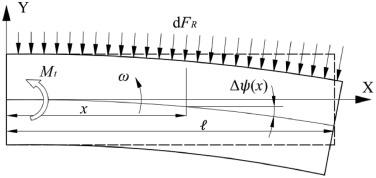
Fig. 1. Schematic diagram of load bearing and bending deformation during hull girder turning. |
According to the theory of fluid mechanics and the general form of ship resistance formula [20], setting the hull draft as , the resistance exerted by seawater on the cross-section element at x of the hull structure is:
where, is the resistance coefficient of the hull during turning, is the density of water and is the relative sea water velocity of the cross-section element at x when the hull turns.
Since ships are usually designed to have sufficient rigidity and bending elastic deformation is small, the turning angular velocity all over the hull can be approximated as , and the above formula can also be expressed as:
The relationship between the seawater resistance of the cross-section element at x, the hydrodynamic characteristics of the hull and steering angular velocity is obtained. Therefore, the load exerted by seawater resistance along the side of the hull during the turning process can be calculated.
4.2. Derivation of azimuthal bending deformation formula
In the process of a ship turning at a constant angular velocity, the hull is continuously subjected to the action of water resistance to produce azimuthal bending deformation. At the same time, in the process of a ship turning with angular acceleration, the hull also be subject to the action of inertial force to produce azimuthal bending deformation. At this point, the longitudinal axis of the hull will become a deflection curve y=y (x) in the xy plane. Since the ship has enough rigidity and the elastic deformation angle is very small, the differential relationship between the bending deformation angle at position x and the deflection y is:
Considering that the width of the cross-section of the hull is far less than the length and the hull has sufficient strength. In the process of hull turning, the relationship between the bending moment of the structural cross-section and the deflection y of the hull can be expressed by the Euler–Bernoulli bending equation [21]:
where, is the flexural rigidity.
The bending angle can be obtained by integrating formula (5):
where, is the integral constant.
Since the hull in the static state will not undergo azimuthal bending deformation, according to the bending moment superposition principle of beams, the total bending moment of the hull structure section is equal to the sum of the bending moment under the action of water resistance in constant angular velocity turning and the bending moment under the action of inertial force in acceleration turning. The cross-section bending moment at x of the hull structure is:
where, is the bending moment under the action of water resistance and is the bending moment under the action of inertia force.
(1) Solve
Let the length of the ship be , according to the conclusion in Section 4.1, and the sign function is introduced to reflect the direction of the bending moment. When the hull turns at the angular velocity , the bending moment at x under the action of water resistance is:
(2) Solve
Let be the moment of inertia of the hull. When the hull turns at the angular acceleration under the action of moment , the bending moment at x under the action of inertia force is:
To sum up, the total bending moment of the section at x of the hull structure is:
Bring formula (10) into formula (6) to get:
The deformation coefficient related to angular velocity at position x of the hull structure is defined as , and the deformation coefficient related to angular acceleration is defined as . According to the boundary condition of when the hull is completely static and there is no bending deformation in the azimuth, where and , it can be concluded that the integral constant is equal to 0. Thus, the theorem formula of hull turning motion and azimuth bending deformation caused by the structural deflection can be obtained.
In order to distinguish the derived theorem formula from other theoretical methods, it is recorded as Qu's bending deformation formula:
Theorem (Qu's bending deformation formula): For the hull simplified as an equal cross-section beam with uniform mass and length , where is the flexural rigidity of the hull structure, is the moment of inertia of the whole ship, is the turning resistance coefficient of the ship, is the water density, is the hull draft, and and are the turning angular velocity and angular acceleration of the hull, under the combined action of the ship's maneuvering and random wave, the hull structure will undergo azimuthal bending deformation with the turning movement. The deformation angle at with the stern as the origin is:
where
It can be seen from the formula (12) that in the short-period elastic deformation of the hull structure, the deformation coefficients and are time-independent parameters, only related to ship type design, structural material, draft, navigation characteristics and measurement position. For specific ships that normally sail at sea, the deformation coefficient at the measuring position changes slightly and can be considered a constant.
The above derivation has obtained the azimuthal bending deformation formula of the hull structure simplified as an equal cross-section beam with uniform mass. This formula clearly reveals the objective law between hull deformation and steering motion. That is to say, the hull steering thrust and wave force will be reflected in the hull deformation and turning movement in the final analysis.
In fact, the material and the structure of the cabin, deck, and the route of the underwater part to transfer the force to other parts when turning left and right are much more complex than the constant section beam. Although most ship structures generally have good symmetry along the longitudinal axis, there is still asymmetry in some local structural parts that deviate from the longitudinal symmetry plane, especially some special ships originally built according to the asymmetric design. Due to the asymmetry of the structure, the rigidity of the stressed structure is different when the ship turns left and right. The load imposed by the external force on the structure is distributed in proportion to the rigidity, which will produce different degrees of deformation. Moreover, ship structures are generally statically indeterminate, and their load distribution is related to the direction of the force. The position and direction of the external force are different when turning left and right, and there is the problem of whether the asymmetric structural parts participate in the stress. These are all reflected in the formula that the actual hull bending rigidity value is different when turning left and right. It can be said that the asymmetric deformation of the hull structure is general, and the symmetric deformation is only a special case.
Therefore, according to the asymmetric deformation of the ship structure, for the mth measuring point of the ship structure, it is necessary to modify the Qu's bending deformation formula according to the turning direction of the ship, where represents a right turn, and represents a left turn. The modified formula is named Qu's bending deformation correction formula, namely:
Qu's bending deformation correction formula
where, and are the structural deformation coefficient at the mth measuring point when the ship turns right and left, respectively. So far, the structural azimuth deformation correction formula at the measuring point position based on the actual ship characteristics has been obtained.
In the INS transfer alignment, the heading angle output by the ship's master INS plus the azimuth angle between the master INS and the slave INS in the inertial coordinate system obtained by other accurate measurement means or guaranteed by the installation base, is transferred to the slave INS for the heading angle setting after the azimuth bending deformation correction, which can achieve fast and high-precision heading transfer alignment.
4.3. Determination of deformation correction coefficients
From the definition of deformation correction coefficients and the contents of various parameters, it is difficult to obtain the values of various parameters in the deformation coefficient of a ship through theoretical calculation. However, if the deformation of the relevant position of the hull structure is measured by the sea trial, then by using the law revealed by the deformation correction formula, the deformation coefficients can be directly obtained.
Therefore, during the sea trial, the ship needs to make at least one S-shaped maneuver including complete left and right turns at the maximum turning angular speed in normal navigation, according to the specially designed maneuvering route to stimulate the hull deformation, to obtain a complete set of correction coefficients.
When sorting out the collected deformation data of the relevant position of the ship deck and the corresponding angular velocity and angular acceleration data, it is first necessary to classify and process the ship navigation and deformation data in chronological order according to the situation of and .
Assume that the measured deformation angle data at x of the hull is when , and when . Then take and as variables, and fit the correction coefficients according to Qu's bending deformation correction formula, namely:
Let ,. Because the correction coefficient at the determined position of the hull structure is constant, the least square method is used to solve and respectively to minimize the objective function, namely
where
Solve Eq. (15) to obtain:
Take and as deformation correction coefficients and of corresponding measuring points, which can be used for azimuth deformation correction.
Generally, the number of navigation measurements is limited, and the coefficients solved will have certain dispersion. Therefore, when multiple-leg data can be obtained, the average value of deformation correction coefficients should be taken. When the turning angular velocity and angular acceleration of different legs are significantly different, the data with larger angular velocity and angular acceleration shall be selected to solve the correction coefficients.
5. Real ship verification
5.1. S‐shape maneuvering test in the sea trial
Three typical positions on the deck of a large ship were selected for measurement. The first is located at the basically symmetrical part of the hull structure, namely P1, near the central axis of the bow; the second position, P2, is located on the right side of the stern, where the structural rigidity is weak and deviates from the central axis of the ship; The last position with strong structural rigidity deviating from the central axis of the ship, namely P3, is close to the left side of the stern. The specially designed measuring equipment is used to measure and calibrate the azimuth for three positions on the ship deck at the wharf, and obtain the azimuth zero position of the local coordinate system relative to the ship coordinate system.
The ship performs an S-shaped maneuver after entering the sea area for testing. At this time, the specially designed measuring equipment was used to fully record and measure the local coordinate system heading change data and the inertial navigation heading data of the ship, and the hull azimuthal bending deformation angle data and curves of each measurement point were obtained.
5.2. Calculation of correction coefficient and deformation correction
The method in Section 4.3 was used to process the measurement data and obtain the corresponding coefficients of the correction formula for the azimuth deformation of the hull structure at three positions on the deck (P1, P2, and P3). The coefficients were used for real-time correction of the azimuth deformation. Fig. 2, Fig. 3, Fig. 4 showed the measured heading error curve and the corrected heading error curve under the influence of hull structural deformation at P1, P2, and P3 when the ship turns.
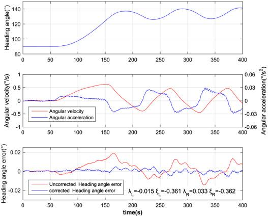
Fig. 2. Heading angle error caused by hull deformation at P1 position and corrected curve. |
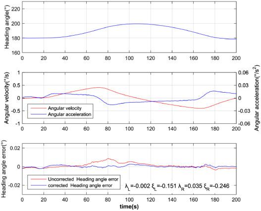
Fig. 3. Heading angle error caused by hull deformation at P2 position and corrected curve. |
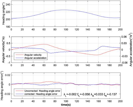
Fig. 4. Heading angle error caused by hull deformation at P3 position and corrected curve. |
It can be seen from the figures that after the correction of the heading error caused by the hull bending deformation, the structural flexural deformation error in the azimuth caused by the hull turning movement is basically eliminated. The error caused by the remaining high-order vibration is basically a small amount of zero mean value, which can meet the requirements of high-precision heading transmission after smooth filtering.
6. Conclusion
From the theoretical formula and the curve before and after the correction of the hull structure deformation measured at sea, we could extract the following conclusions. First, the hull deformation is related to the angular velocity and angular acceleration, and the maximum hull deformation occurs at the maximum angular acceleration. Second, the direction of hull deformation during navigation is basically consistent with the direction of angular velocity, with only a certain time lag. This also proves that the turning and deformation of large ships are mainly caused by lateral hydrodynamic forces, rather than direct rudder forces. Third, the deformation of the asymmetric part of the hull shows obvious asymmetry, and the deformation size is closely related to the hull material, the overall structure, and the local structure form near the measurement position, etc. Fourth, the bending deformation of the local position structure caused by the combined the ship maneuvering and random wave can be basically eliminated according to the Qu's bending deformation correction formula. The high-order vibration component modulated on the corrected heading angle error curve is basically a small amount and can be regarded as zero mean white noise.
The theory and practice have proved that the relationship between the angular motion and angular deformation of the hull is derived based on the analysis of the equivalent load exerted by the hydrodynamic forces and inertia force on the hull structure during turning, revealing the objective law of the azimuthal bending deformation of the hull structure. Based on these and combined with the sea trial, the correction coefficients of the ship turning left and right are obtained, which can greatly reduce the impact of the hull structure flexural deformation on the local position heading angle and meet the needs of real-time high-precision heading transmission. This theory and method provide technical support for establishing high-precision distributed digital reference in the field of transfer alignment of INS on moving base and the application of heading angle transfer of other shipborne equipment.
Declaration of Competing Interest
The authors declare that they have no known competing financial interests or personal relationships that could have appeared to influence the work reported in this paper.
