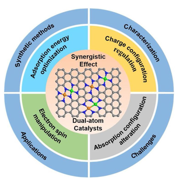
Highlights
1 Introduction
Fig. 1 a Advantages of dual-atom catalysts over single-atom catalysts. b-d Schematic diagram of the classification of DACs. The green ball and the orange ball represent the metal atoms M and M’, respectively. The white ball represents N or O atom. The blue cube represents the substrate |
2 Classification of Dual-Atom Catalysts
2.1 DACs with No Contact Sites
2.2 DACs with Metal-Metal Bonds
2.3 DACs with Metal Sites Bridged by Nonmetal Atoms
3 Dual Metal Sites Synergistic Effect
3.1 Synergistic Effect in Homonuclear DACs
3.1.1 Optimization on the Adsorption Configurations of Reactants and Intermediates
Fig. 3 a Free energy diagram for ORR on a single Fe site of molecular FePc. b Free energy diagram for ORR on two adjacent Fe sites of FePc nanorods [63]. Copyright 2022 American Chemical Society. c Partial density of state (pDOS) of Fe 3d orbitals. d Charge density difference. e pDOS for Fe-3dyz/dz2/dxz orbitals and adsorbed CO orbitals. f Orbital interaction between Fe-3d (dz2 and dxz/dyz) and adsorbed CO (5σ and 2π*) [30]. Copyright 2022 American Chemical Society. g Least-squares curve-fitting analysis of operando EXAFS spectra at the Ni K-edge. h Comparison between the Ni K-edge XANES experimental spectra (solid lines) and the theoretical spectra (dashed lines) calculated with the depicted structures (insert). i Free energy diagrams for CO2 electroreduction to CO. j Calculated Gibbs free energy diagrams for the HER and CO2 electroreduction to HCOOH on O − Ni2 − N6. k Proposed reaction pathways on O − Ni2 − N6 [37]. Copyright 2022 American Chemical Society |
3.1.2 Alteration of the Charge Configuration of the Active Site
3.1.3 Evolution of More Favourable Active Site
3.2 Synergistic Effect in Heteronuclear DACs
3.2.1 Redistribution of Charge
Fig. 4 a ORR theoretical overpotential (ηORR) versus ΔG*OOH. b Volcano plots of the OER theoretical overpotential (ηOER) versus adsorption free energy difference (ΔG*OOH—ΔG*O). c Number of electrons (Ne) lost from an Fe, Co, or Ni atom [81]. Copyright 2022 American Chemical Society. d Density of states of Fe 3d for Fe-SAC and NiFe-DASC, of Ni 3d for Ni-SAC and NiFe-DASC. e Schematic illustration of orbital interactions between adsorbed CO (5σ and 2π*) and 3d orbital (dz2, dxz/dyz) of Fe site in e Fe-SAC and f NiFe-DASC [83]. Copyright 2021 Springer Nature |
3.2.2 Regulation of d Orbitals of Metal Sites
3.2.3 Manipulation of Electronic Spin Configurations
Fig. 5 Schematic electronic structures of a Fe-N-C and b Fe/Zn-N-C [88]. Copyright 2022 Royal Society of Chemistry. c Comparison of magnetic moment and ΔGOH*. d Fe 3d DOS of Fe1/Fe1-2 and Cu1/Fe1-2. e DOS of the five Fe 3d orbitals in Cu1/Fe1-2 [89]. Copyright 2022 Wiley-VCH GmbH. f Geometric structure and corresponding electron density difference of Fe-Ni-N-P-C. g Overpotential of OOH* formation [91]. Copyright 2021 Elsevier Ltd |
3.2.4 Induction of Different Adsorption Configurations
4 Synthetic Methods of DACs
4.1 Homonuclear DACs
4.2 Heteronuclear DACs
5 Characterization of DACs
5.1 Aberration-Corrected Scanning Transmission Electron Microscopy (AC-STEM)
Fig. 11 a HAADF-STEM image of Cu/Ni-NC. b Line-scanning intensity profiles corresponding to the highlights in a. c EELS diagram of Cu/Ni-NC [47]. Copyright 2023 Wiley-VCH GmbH. d HAADF-STEM image of NiCu-NC. e NiCu atomic pair and the corresponding 3D intensity profile. f EELS diagram of NiCu-NC [108]. Copyright 2023 Wiley-VCH GmbH |
5.2 X-ray Techniques
Fig. 12 a Fe K-edge XANES spectra. b EXAFS fitting curve of Fe in Fe-Co DACs spectra. c k-space experimental EXAFS spectra and fitting curves of Fe in Fe-Co DACs [46]. Copyright 2023 Springer Nature. d Fe K-edge XANES spectra. e FT-EXAFS spectra. f Corresponding fitting in R space of FeCo-NSC and FePc at Fe K-edge [43]. Copyright 2022 Elsevier Ltd |
5.3 In Situ Characterization
Fig. 13 a Pt L3-edge and b Fe K-edge FT-EXAFS spectra and the corresponding fitting curves under different potentials. c The fitting results of the coordination number. In situ SR-FTIR characterizations for d Pt = N2 = Fe ABA and e Pt AMS. f FTIR absorption stretching for Pt = N2 = Fe ABA and Pt AMS [40]. Copyright 2022 Springer Nature |
6 Application of DACs in Electrocatalysis
6.1 Oxygen Reduction Reaction (ORR)
Fig. 14 a The optimized structure model, b aberration-corrected HAADF-STEM image, c 57Fe Mossbauer spectrum. d magnetic susceptibility of Fe,Mn/N-C. e LSV curves of Fe,Mn/N-C, Fe/N-C, Mn/N-C and Pt/C catalyst in 0.1 M HClO4 solution [132]. Copyright 2021 Springer Nature. f Structure model, g HAADF-STEM image of FeCo-NC. h SCV measurements, i Tafel plots of the as-prepared catalysts 0.1 M KOH solution [128]. Copyright 2022 American Chemical Society |
Table 1 The activity of DACs for ORR and their performance in different applications |
| Catalyst | E1/2 (V vs. RHE) | Electrolyte | Application | Peak power density (mW cm−2) | Refs |
|---|---|---|---|---|---|
| Fe-Se/NC | 0.925 | 0.1 M KOH | Zn-air batteries | 135 | [137] |
| FeCo-NSC | 0.86 | 0.1 M KOH | Zn-air batteries | 152.8 | [43] |
| FeCo-NC | 0.877 | 0.1 M KOH | Zn-air batteries | 372 | [128] |
| CoFe-NG | 0.952 | 0.1 M KOH | Zn-air batteries | 230 | [138] |
| Fe,Zn-N-C | 0.867 | 0.1 M KOH | Zn-air batteries | 138 | [139] |
| Fe2DAC | 0.898 | 0.1 M KOH | Zn-air batteries | 325.8 | [140] |
| D-FeCo-DAs-N-C | 0.927 | 0.1 M KOH | Zn-air batteries | 259 | [141] |
| FeCo/DA@NC | 0.84 | 0.1 M KOH | Zn-air batteries | 110.3 | [142] |
| Cu-Co/NC | 0.92 | 0.1 M KOH | Zn-air batteries | 295.9 | [143] |
| Zn/Fe-NC | 0.875 | 0.1 M KOH | Zn-air batteries | 186.2 | [144] |
| Fe-Mn-N-C | 0.93 | 0.1 M KOH | AEMFCs | 1321 | [36] |
| FeCu-NC | 0.882 | 0.1 M KOH | AEMFCs | 910 | [145] |
| FeCo-MHs | 0.95 | 0.1 M KOH | AEMFCs | 604.9 | [146] |
| Fe-Mn-N-C | 0.79 | 0.1 M HClO4 | PEMFCs* | 1048 | [36] |
| Fe, Cu DAs-NC | 0.80 | 0.5 M H2SO4 | PEMFCs | 875 | [147] |
| Fe&Pd-C/N | 0.808 | 0.5 m H2SO4 | PEMFCs | 362 | [148] |
| Cu-Co/NC | 0.85 | 0.5 m H2SO4 | PEMFCs | 963 | [143] |
| FeMo-N-C | 0.84 | 0.1 M HClO4 | PEMFCs | 460 | [149] |
| FeCe-SAD/HPNC | 0.81 | 0.1 M HClO4 | PEMFCs | 771 | [150] |
| (Au-Co) DP-NPAs | 0.82 | 0.1 M HClO4 | PEMFCs | 490 | [84] |
*PEMFC represents proton exchange membrane fuel cell |
6.2 Carbon Dioxide Reduction Reaction (CO2RR)
Fig. 15 a Illustration and b HAADF-STEM image of CoCu-DASC. c Line-scanning intensity profiles obtained from the site A and B in panel b. d Faradaic efficiencies for electrochemical reduction of CO2 to CO, e CO partial current density in flow cell and f free energy profiles of CoCu-DASC and corresponding SACs [161]. Copyright 2022 Wiley-VCH GmbH g Illustration, h LSV curves, i Faraday efficiencies for electrochemical reduction of CO2 to CO and j free energy profiles of Ni2 DACs and Ni SAC [162]. Copyright 2022 Wiley-VCH GmbH |
Fig. 16 a Schematic diagram of Pt-Ru dimers on NCNT. b HAADF-STEM images of Pt-Ru dimers. c K2-weighted magnitude of Fourier transform spectra of Pt-Ru dimers and Pt single atoms. d HER polarization curves and e normalized mass activity of Pt-Ru dimers and Pt single atoms at 0.05 V [171]. Copyright 2019 Springer Nature f DFT calculations of formation energies and d-band centre for bimetallic single-atom dimers. g HAADF-STEM image of NiCo-SAD-NC. h Ni K-edge and i Co K-edge FT-EXAFS spectra. j LSV curves and k corresponding Tafel plots [172]. Copyright 2021 Springer Nature |
6.3 Hydrogen Evolution Reaction (HER)
6.4 Nitrogen Reduction Reaction (NRR)
Fig. 17 a Illustration of FeM-GDYs. b Volcano relationship between the UL and Eads(*NH2). c Colour contour plot of ΔG(*NNH) and ΔG(*NH2) [181]. Copyright 2021 Royal Society of Chemistry. d HAADF-STEM image of PdCu/NC. e NH3 yield rates and f FEs of Pd/NC, Cu/NC and PdCu/ NC [184]. Copyright 2021 Wiley-VCH GmbH |
6.5 Oxygen Evolution Reaction (OER)
Fig. 18 a HAADF-STEM images of Co/Fe-SNC800. b Illustration of Co/Fe dual-metal site. c LSV curves of Fe-SNC800, Co-SNC800, Co/Fe-SNC800 at 1600 rpm. d Chronopotentiometry plots of Co/Fe-SNC800. e Reaction energy diagram of Co/Fe-SNC and Co-SNC under U = 0 V [196]. Copyright 2023 Royal Society of Chemistry. f Illustration of a-NiCo/NC. g LSV curves of a-NiCo/NC, NiCo NPs/NC, a-Ni/NC, a-Co/NC, RuO2 at 1600 rpm. h Chronopotentiometry plots of a-NiCo/NC, NiCo NPs/NC, RuO2. i Free energy diagram of a-NiCo/NC, a-Ni/NC, a-Co/NC under U = 0 V [85]. Copyright 2022 Wiley-VCH GmbH |
6.6 Other Reactions
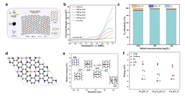
Fig. 19 a Schematic synthesis of NiCu3-N-C DAC. b LSV curves in 1 M NaOH + 0.2 M NH4Cl. c N2 selectivity of NiCu3-N-C DAC in different initial concentrations of ammonia. Copyright 2023 Elsevier Ltd. d Preferable configuration of two metal atoms anchored C2N (C, grey; N, blue; gold, M1; pink, M2). e Reaction pathways based on the TER mechanism. f d-band centres and the adsorption energies of CO, O2, and O for the Fe2@C2N, Fe1Cu1@C2N and Cu2@C2N [209]. Copyright 2019 Wiley-VCH GmbH |


