HIGHLIGHTS
1 Introduction
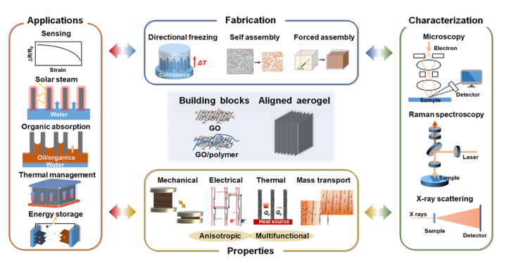
Fig. 1 Overview of the highly aligned graphene aerogels for multifunctional composites, from multiscale assembly of aerogel precursors to anisotropic structures, multifunctional properties, and applications. Directional freeze drying. Reproduced under the terms of the Creative Commons CC BY-NC license [27]. Copyright 2018, American Chemical Society. Self-assembly. Reproduced with permission [28]. Copyright 2015, Wiley-VCH. Forced assembly. Reproduced with permission [29]. Copyright 2022, Wiley-VCH. Microscopy, Solar steam. Reproduced with permission [30]. Copyright 2017, American Chemical Society. Raman spectroscopy. Reproduced with permission [31]. Copyright 2011, American Chemical Society. X-ray scattering. Reproduced with permission [32]. Copyright 2020, Wiley-VCH. Mechanical. Reproduced with permission [33]. Copyright 2018, Elsevier. Thermal. Reproduced with permission [34]. Copyright 2022, American Chemical Society. Sensing. Reproduced with permission [35]. Copyright 2021, Elsevier. Organic absorption. Reproduced with permission [36]. Copyright 2021, American Chemical Society. Thermal management. Reproduced with permission [37]. Copyright 2017, American Chemical Society. Energy storage. Reproduced with permission [38]. Copyright 2020, American Chemical Society |
2 Preparation of Aligned Graphene Aerogels
Fig. 2 Summary of the most applied techniques for the fabrication of highly aligned graphene aerogels |
2.1 Directional Freeze Casting Techniques
Fig. 3 Freeze casting process, mechanism, and morphologies. a Schematic process of freeze casting for the fabrication of aligned graphene aerogel; b-e The rearrangement of particles in suspensions during the freezing process in different relative values of the freezing velocity (v) and the critical freezing front velocity (vcr). Reproduced with permission [57]. Copyright 2020, Wiley-VCH. f SEM image of aligned aerogels with lamellar walls at v < vcr. Reproduced with permission [61]. Copyright 2021, Elsevier. g SEM images of fine-scale interconnected porous alignments at v ≥ vcr. Reproduced with permission [42]. Copyright 2018, American Chemical Society. h Effects of the freezing temperature (or the freezing speed) on the alignment of graphene aerogels. Reproduced with permission [62]. Copyright 2021, Elsevier. i-k Effects of the lateral size of GO building blocks on the alignment of graphene aerogels. Reproduced with permission [65]. Copyright 2018, American Chemical Society |
2.1.1 Unidirectional Freeze Casting
Fig. 4 Unidirectional freeze casting techniques and corresponding morphologies. a Gradual immersion of GO suspensions in cooling bath. Reproduced with permission [70]. Copyright 2009, Wiley-VCH. b A schematic apparatus for unidirectional freeze casting of GO suspensions and the formation mechanism of the aligned GO walls in aerogel. Reproduced with permission [5]. Copyright 2016, American Chemical Society. c Schematics of lateral unidirectional freeze casting. Reproduced with permission [85]. Copyright 2022, The Authors, published by Springer Nature. d-g Typical SEM images of unidirectionally freeze-cast graphene aerogels observed from different directions. The left two reproduced with permission [70]. Copyright 2009, Wiley-VCH. The right two reproduced with permission [83]. Copyright 2022, Wiley-VCH |
2.1.2 Bidirectional Freeze Casting
Fig. 5 a-c Schematic illustrations of three typical bidirectional freeze casting apparatus and processes for the fabrication of highly aligned graphene aerogels. Reproduced with permission [27,87,88]. Copyright 2018, American Chemical Society. Copyright 2021, Wiley-VCH. Copyright 2020, Elsevier. Schematic and morphology comparisons of aerogels prepared using d, e bidirectional freezing, f, g unidirectional freezing and h, i common freezing. Reproduced with permission [88]. Copyright 2020, Elsevier |
2.1.3 Radial Freeze Casting
Fig. 6 Illustration of a freezing setup for fabricating graphene aerogels with radial orientation, b the temperature gradient, c the freezing-drying process, and d SEM morphologies of a radiating graphene aerogel. Reproduced with permission [99]. Copyright 2018, American Chemical Society. e Schematic diagram of radial freeze casting of rGO hydrogel and f microstructure of corresponding aerogels. Reproduced under the terms of the Creative Commons CC BY license [102]. Copyright 2021, The Authors, published by Springer Nature. g Fabrication of radiating graphene aerogel spheres by immersing GO droplets into liquid nitrogen. Reproduced with permission [103]. Copyright 2017, American Chemical Society; and h, i their cross-sectional microstructure. Reproduced with permission [104]. Copyright 2016, American Chemical Society |
2.2 Self-Assembly Induced Alignment
Fig. 7 GO LC which is the prerequisite of self-assembly induced graphene alignment. a The transition of GO suspensions from isotropic to nematic LCs with increasing concentration. Reproduced with permission [107]. Copyright 2016, Wiley-VCH. b Nematic phase fraction in GO suspensions against the concentration. Reproduced with permission [109]. Copyright 2014, American Chemical Society. c, d Typical nematic texture and freeze-dried morphology of GO LCs. Reproduced with permission [110]. Copyright 2011, Wiley-VCH. Polarized optical microscopy and Cryo-SEM images of GO LCs in the e, f lateral and g, h center regions, showing helical structures. Reproduced with permission [113]. Copyright 2011, The Authors, published by Springer Nature |
Fig. 8 Typical self-assembly strategies for the fabrication of highly aligned graphene aerogels. a Hydrothermal treatment induced self-assembly of GO sheets for the fabrication of graphene aerogels and b-d corresponding aerogel morphologies fabricating using different GO concentrations. Reproduced with permission [11]. Copyright 2015, American Chemical Society. e-i Self-assembly of base-induced highly ordered GO LCs and microscopic structures of the LC and aerogel. Reproduced with permission [28]. Copyright 2015, Wiley-VCH. j-l Vacuum filtration- and crosslinking-assisted self-assembly. Reproduced with permission [123]. Copyright 2017, Wiley-VCH |
2.3 Shear-Induced Alignment
Fig. 9 Shearing-induced GO rearrangement in LCs. a Macroscopic observation of GO suspensions under shearing. Reproduced with permission [129]. Copyright 2021, American Chemical Society. b Relaxation of GO LCs after scratching and c-e corresponding mechanisms revealing; and f patterned GO LCs constructed by shearing microlithography. Reproduced under the terms of the Creative Commons CC BY license [131]. Copyright 2019, The Authors, published by Springer Nature |
Fig. 10 Typical shear-induced alignment for fabricating aligned graphene aerogels. Flow induced alignment: a-c Alignment during ejecting from a nozzle Reproduced with permission [55,133]. Copyright 2012, 2014, American Chemical Society; and d Layer-by-layer 3D printing through a slit extrusion head Reproduced with permission [29]. Copyright 2022, Wiley-VCH. Shearing microlithography: e microwire shearing. Reproduced with permission [137]. Copyright 2023, Wiley-VCH; and f-h scratching the GO LC using an immersed microprobe Reproduced with permission [131]. Copyright 2019, The Authors, published by Springer Nature |
2.4 Further Enhancement of Alignment
2.5 Comparison of the Aligning Techniques
Table 1 Comparisons of different aligning techniques for graphene aerogels |
| Aligning techniques | Directional freeze casting | Self-assembly | Shearing forced alignment | ||
|---|---|---|---|---|---|
| Unidirectional | Bidirectional | Radial | |||
| Driving force | Growth of ice templates | Reduction-induced gelation | Shear force | ||
| Alignment | Unidirectional | Bidirectional | Radial | Inherent from GO LCs | Along shearing direction |
| Morphologies | Tubular | Lamellar | Radially lamellar | Multi-domain alignment | Tubular or lamellar |
| Advantages | Long-range aligned; precise control over alignment; scalable | Easy-processing; versatile | Scalable; large-size; patternable alignment | ||
| Shortcomings | Careful optimization of freezing parameters is required | Limit in long-range alignment; less anisotropic | High-concentration GO LC is required | ||
| Advantageous applications | Electrochemical; Organic absorption | Superelasticity related (i.e. pressure sensing); thermal management | Organic absorption | Electrochemical | Thermal management |
| Relative fabrication cost | Relatively low | Medium | High | ||
2.6 Fabrication of Highly Aligned Graphene Aerogel/Polymer Composites
Fig. 12 Fabrication of aligned graphene aerogel-based composites via a-c post-infiltration of polymer matrix in the preconstructed aligned graphene aerogels. Reproduced with permission [154]. Copyright 2019, Elsevier; and d directional freeze-drying of GO/polymer suspensions. Reproduced under the terms of the Creative Commons CC BY license [156]. Copyright 2016, The Authors, published by Springer Nature. e Nanoscopic alignment of graphene sheets in the aligned composite skeleton. Reproduced with permission [157]. Copyright 2017, Elsevier |
3 Fundamental Properties
3.1 Anisotropic Properties
Fig. 13 Anisotropic properties of highly aligned graphene aerogels and their composites. a, b Illustrations of the coordinate directions. Anisotropic properties and relevant mechanism: c-e mechanical. Reproduced with permission [33]. Copyright 2018, Elsevier. f, g Electrical. Reproduced with permission [5]. Copyright 2016, American Chemical Society. h, i Thermal. Reproduced with permission [34]. Copyright 2022, American Chemical Society. Reproduced under the terms of the Creative Commons CC BY license [166]. Copyright 2020, The Authors, published by Springer Nature. j, k Mass transport. l, m EMI shielding properties. Reproduced with permission [171]. Copyright 2016, American Chemical Society |
3.2 Contributions of Alignment to Physical Properties of Composites
3.2.1 Electrical Conductivity
Fig. 14 Electrical percolation and conductivity of graphene/polymer composites. a Schematic illustrations of the percolation theory. Reproduced with permission [193]. Copyright 2016, Society of Chemical Industry. b Percolation threshold of polymer composites reinforced with different fillers: CVD-grown graphene [176,177], aligned graphene aerogel [5,11,65], random graphene aerogel [178,179], dispersed graphene [180,181,182,183,184,185], and segregated graphene [186,187,188,189]. c Electrical conductivity of polymer composites reinforced with different fillers: aligned graphene aerogel [5,65,171,190], random graphene aerogel [178,191,192], CVD-grown graphene network [177,194,195], dispersed graphene [180,196,197,198,199], and segregated graphene [187,188,189,200] |
3.2.2 Fracture Toughness
Fig. 15 Fracture toughness of graphene/epoxy composites. a Increment in fracture toughness of polymer composites reinforced with different fillers: CVD-grown graphene [177,194,195], aligned graphene aerogel [11,42,65,143,166,201,202], random graphene aerogel [65] and dispersed graphene [203,204,205]. b-d Fractured cross-sectional SEM images and corresponding schematic crack prorogation process of aligned graphene aerogel/epoxy composite. Reproduced with permission [11]. Copyright 2015, American Chemical Society |
3.2.3 Thermal Conductivity
Fig. 16 Thermal conductivity of graphene/polymer composites. a Thermal conductivity of graphene/polymer composites reinforced with different fillers: aligned graphene aerogel [64,74,102,137,166,201,207,208,221], random graphene aerogel [208,209,210], dispersed graphene [211,212,213], segregated graphene [214,215,216,217], and CVD-grown graphene [195,218,219,220]. Schematic illustrations of thermal conduction in b defective rGO and c well-crystalline graphene sheets. Reproduced with permission [15]. Copyright 2021, Elsevier. d Schematic mechanisms of thermal conduction in highly aligned graphene aerogel/polymer composites. The solid and hollow symbols in a represent the graphene and rGO building blocks in the thermally conductive graphene network, respectively |
4 Quantitative Characterization Techniques of the Graphene Alignment
4.1 SEM Image-Based Orientation Distribution Analysis
Fig. 17 Quantitative analysis of the alignment in graphene aerogels using filler orientation distributions. Reproduced with permission [5]. Copyright 2016, American Chemical Society |
4.2 Polarized Raman Spectroscopy
Fig. 18 Qualitative and Quantitative analysis of graphene alignment by polarized Raman spectroscopy. a Schematic illustration of a typical polarized Raman spectroscopy. Reproduced under the terms of the Creative Commons CC BY license [226]. Copyright 2016, The Authors, published by Springer Nature. b-e Qualitative analysis of graphene alignment. Reproduced with permission [180]. Copyright 2013, Elsevier. Quantitative analysis of graphene alignment: f The Cartesian coordinate system with the sample geometries. Reproduced under the terms of the Creative Commons CC-BY license [230]. Copyright 2015, The Authors, published by Elsevier. g The local orientation of graphene in specimens, h coordinates of the specimen relative to the experimental measurement parameters. Reproduced with permission. Reproduced under the terms of the Creative Commons CC-BY license.[231]. Copyright 2015, The Authors, published by Elsevier. 3D Raman intensity for i VV and j VH polarization configurations, and k relative G band intensity. Reproduced with permission [31]. Copyright 2011, American Chemical Society. l Intensity variation for laser beam propagation in X and Z directions of graphene paper, and m orientation distribution function of HOPG and graphene paper. Reproduced under the terms of the Creative Commons CC-BY license [231]. Copyright 2015, The Authors, published by Elsevier. The designations VV and VH in i-k refer to the parallel and the perpendicular polarization of incident and scattered rays, respectively |
4.3 X-ray Scattering
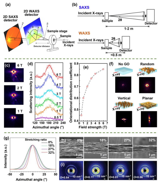
Fig. 19 a, b Schematic illustrations of SAXS and WAXS techniques. Reproduced with permission [236,237]. Copyright 2013, Elsevier. Copyright 2016, AIP publishing. Assessment of graphene alignment through SAXS: c 2D SAXS patterns, d the azimuthal dependence of scattering intensity, e orientational distribution coefficient of graphene-based materials fabricated under different magnetic field strengths; and f SAXS analysis of composites featuring diverse graphene alignment. Reproduced under the terms of the PNAS License [245]. Copyright 2017, National Academy of Sciences. Evaluation of graphene alignment using WAXS: g azimuthal scan profiles, h SEM images, and i 2D WAXS patterns of graphene fibers with different stretching ratios. Reproduced with permission [32]. Copyright 2020, Wiley-VCH |
4.4 Comparison of the Characterization Techniques
Table 2 Comparisons of different quantitative characterization techniques of the alignment degree |
| Characterization techniques | SEM-based | Polarized Raman spectroscopy | X-ray scattering |
|---|---|---|---|
| Mechanism | SEM image processing and analyzing | Inelastic scattering of photons | Elastic scattering of X-rays |
| Orientation distribution function | $\langle {cos}^{2}\eta \rangle ={\int }_{0}^{\pi /2}N\left(\eta \right){cos}^{2}\eta sin\eta d\eta$ | $\langle {P}_{i}\left(cos\theta \right)\rangle =\frac{{\int }_{\theta =0}^{\theta =\pi }{P}_{i}\left(cos\theta \right){f}_{N}\left(\theta \right)sin\theta d\theta }{{\int }_{\theta =0}^{\theta =\pi }{f}_{N}\left(\theta \right)sin\theta d\theta }$ | $O=\langle \frac{1}{2}\left(3{{\text{cos}}}^{2}\theta -1\right)\rangle$ |
| Quantifying criterion | $\langle {{\cos }^{2}}\eta \rangle $= 1/3: random | $\langle {P}_{2}({\text{cos}}\theta )\rangle =0$: random | O = 0: random |
| $\langle {{\cos }^{2}}\eta \rangle $= 0 or 1: perfectly aligned | $\langle {P}_{2}({\text{cos}}\theta )\rangle =1$: perfectly aligned | O = 1: perfectly aligned | |
| Scale | Microscale | Micro- to nanoscale | Macro- to nanoscale |
| Information obtained | Alignment; inter-wall spacing | Alignment; structural anisotropy | Alignment; crystallinity; inter-layer spacing |
| Characteristics | Best for visualizing local variations | Local alignment | Comprehensive information |
5 Multifunctional Applications
5.1 Energy Conersion and Storage
5.1.1 Solar-Thermal Energy Conversion
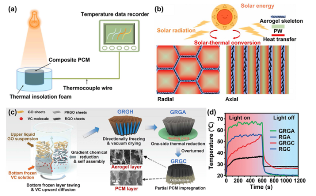
Fig. 20 Solar-thermal energy conversion and solar stream of vertically aligned graphene-based aerogels. Schematic illustration of solar-thermal energy conversion a device and b mechanism. Reproduced with permission [255]. Copyright 2022, Elsevier. c Fabrication and d the surface temperature against sun radiation time of a gradient aligned graphene aerogel-based composites. Reproduced with permission [253]. Copyright 2023, Wiley-VCH |
5.1.2 Battery
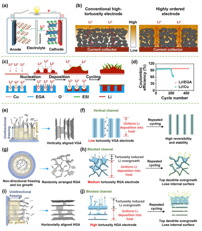
Fig. 21 Highly aligned graphene aerogel-based composites for Li-ion batteries. a Schematic illustration of the Li-ion battery. Reproduced with permission [259]. Copyright 2013, American Chemical Society. b Li ion diffusion in different electrodes. Reproduced with permission [261]. Copyright 2020, Elsevier. c, d Thermally annealed aligned graphene aerogel for Li-batteries to hinder the growth of dendrite. Reproduced with permission [263]. Copyright 2021, Elsevier. e-j Comparison of the Li ion diffusion and dendrite growth in vertically aligned, horizontally aligned, and randomly arranged graphene aerogels. Reproduced with permission [265]. Copyright 2020, Elsevier |
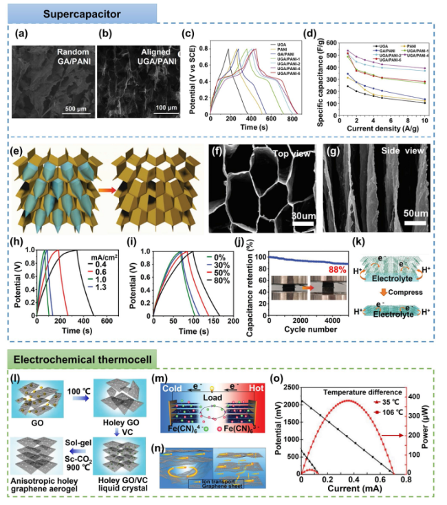
5.1.3 Supercapacitor and Electrochemical Thermocell
Fig. 22 a-d Performances of supercapacitors with random and aligned graphene aerogel-based electrodes. Reproduced with permission [256]. Copyright 2018, Elsevier. e-k Directional freeze-casted graphene-based composite aerogels for compressible supercapacitors. Reproduced under the terms of the Creative Commons Attribution-NonCommercial License [272]. Copyright 2022, The Authors, published by Wiley-VCH. l-o Anisotropic holey graphene aerogel for electrochemical thermocell. Reproduced with permission [274]. Copyright 2019, Wiley-VCH |
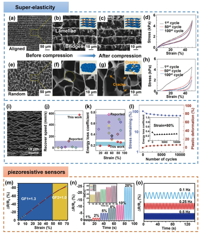
5.2 Super-Elasticity and Piezoresistive Sensors
Fig. 23 Super-elasticity and piezoresistive sensing of highly aligned graphene aerogels. a-h Comparison of the super-elasticity of aligned and random graphene aerogel. Reproduced under the terms of the Creative Commons CC BY-NC license [27]. Copyright 2017, American Chemical Society. i SEM morphology, j, k compressive elasticity and l fatigue resistance of an aligned arc-shaped lamellar graphene aerogel. Reproduced under the terms of the Creative Commons CC BY license [156]. Copyright 2016, The Authors, published by Springer Nature. m-o Super-elastic aligned graphene aerogels applied as piezoresistive sensors. Reproduced with permission [35]. Copyright 2021, Elsevier |
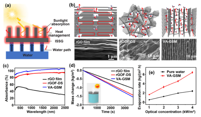
5.3 Solar Steam
Fig. 24 a Design idea of graphene based interfacial solar-steam generation system to enhance water evaporation. Reproduced under the terms of the Creative Commons Attribution License [294]. Copyright 2022, The authors, published by Wiley-VCH. b-e Solar steam of graphene paper, random and aligned graphene aerogel. Reproduced with permission [30]. Copyright 2017, American Chemical Society |
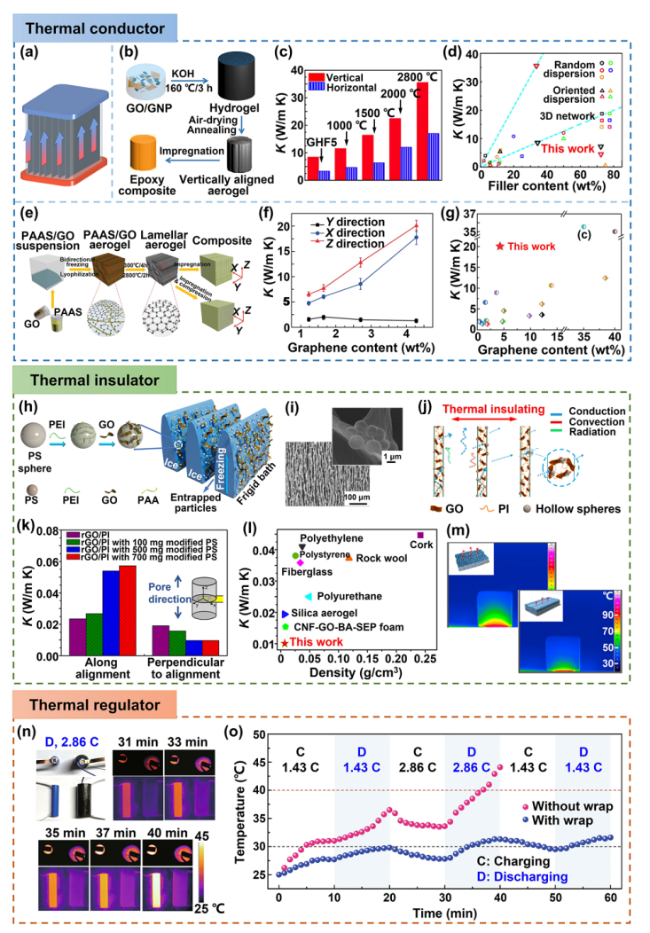
5.4 Thermal Management
Fig. 25 Highly aligned graphene aerogel-based composites applied in thermal management: a-g thermal conductors, h-m thermal insulators, and n, o thermal adjustors. a Vertically aligned graphene aerogel networks for TIMs applications. b-d Thermally conductive air-dried aligned graphene aerogel/epoxy composites. Reproduced with permission [165]. Copyright 2018, American Chemical Society. e-g Lamellar-structured graphene aerogel/epoxy composites for thermal conductors. Reproduced under the terms of the Creative Commons CC BY license [166]. Copyright 2020, The Authors, published by Springer Nature. h-m Highly oriented hierarchical graphene-based aerogels as thermal insulators. Reproduced with permission [37]. Copyright 2017, American Chemical Society. n, o Graphene aerogel/PCM composites for thermal adjusting. Reproduced under the terms of the Creative Commons CC BY license [102]. Copyright 2021, The Authors, published by Springer Nature |
5.5 Organic Absorption
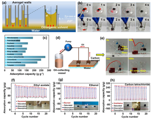
Fig. 26 Absorption of oil or organic solvent of aligned graphene aerogel-based materials. a Capillary absorption mechanism, b absorption process, c absorption capacity, d, e oil water separation by continuous pumping, and recyclability via f squeezing, g burning, and h distilling. Reproduced with permission [36]. Copyright 2021, American Chemical Society |


