Following high-temperature calcination, ANFs transform into CNFs, maintaining the integral 3D network structure (
Fig. 2b). The
α-Fe
2O
3@ANFs was transformed into Fe
3O
4-Fe@CNFs after exposure to high temperature, maintaining 3D network appearance (
Fig. 2d). The ANFs in
α-Fe
2O
3@ANFs act as a skeleton, effectively separating
α-Fe
2O
3 and preventing extensive ceramic sintering. The Al-
α-Fe
2O
3 nanosheets exhibits an ultra-thin 2D structure (
Fig. 2g). Agglomerative sintering was observed when Al-
α-Fe
2O
3 nanosheets alone were calcined into Al-Fe
3O
4 nanosheets in a reducing atmosphere (Fig. S2a). The Fe
3O
4-Fe@CNFs/Al-Fe
3O
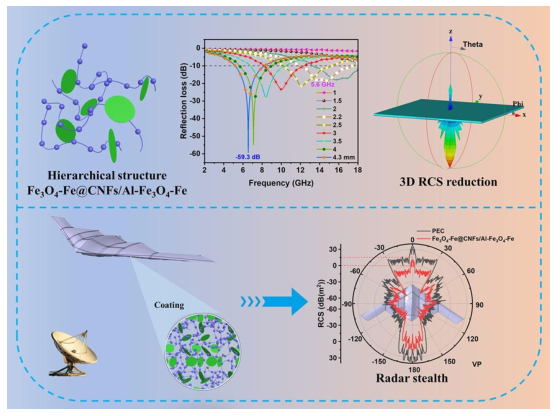
4-Fe nanocomposites present a 3D network structure, with 0D Fe
3O
4-Fe nanoparticles, 1D carbon nanofibers, and 2D Al-Fe
3O
4-Fe nanosheets clearly visible (
Fig. 2f), contributing to excellent electromagnetic wave (EMW) absorption performance in multiple dimensions. Al-Fe
3O
4-Fe was affixed to the Fe
3O
4-Fe@CNFs skeleton, forming a 3D aerogel structure. With decreasing Al-Fe
3O
4-Fe content in Fe
3O
4-Fe@CNFs/Al-Fe
3O
4-Fe
(1:1, 1:2, 1:2.5), morphological deformation and pores emerge attributed to ceramic sintering (Fig. S2b-d). The phases, structures, and components of samples were further analyzed by XRD (
Fig. 2h). The primary diffraction peaks at 24.3°, 33.2°, 35.8°, 41.0°, 54.2°, and 64.1° for
α-Fe
2O
3@ANFs correspond to the crystal planes (012), (104), (110), (113), (116), and (300) of
α-Fe
2O
3 (JCPDS card No. 33-0664), respectively. Similarly, the primary diffraction peaks at 30.1°, 35.4°, 43.1°, and 57.0° for Fe
3O
4-Fe@CNFs and Fe
3O
4-Fe@CNFs/Al-Fe
3O
4-Fe correspond to the crystal planes (220), (311), (400), and (511) of Fe
3O
4 (JCPDS card No. 87-0245), respectively. Notably, there are also 44.6°, 64.9°, and 82.3° correspond to the crystal planes (110), (200), and (211) of Fe (JCPDS card No. 06-0696) in Fe
3O
4-Fe@CNFs and Fe
3O
4-Fe@CNFs/Al-Fe
3O
4-Fe. The major diffraction peaks align with crystal faces
α-Fe
2O
3 and Fe
3O
4.
α-Fe
2O
3@ANFs/Al-
α-Fe
2O
3 was calcined at 700 °C for 4 h to form Fe
3O
4-Fe@CNFs/Al-Fe
3O
4-Fe, with Ar atmosphere during calcination. No reducing gas was introduced during calcining process of Fe
3O
4-Fe@CNFs/Al-Fe
3O
4-Fe nanocomposites, and the nanocomposites underwent self-reduction through their own components. ANFs in the
α-Fe
2O
3@ANFs/Al-
α-Fe
2O
3 were transformed into carbon material CNFs in an inert gas, while CNFs react with
α-Fe
2O
3 in the nanocomposites, reducing it to Fe
3O
4, and some Fe
3O
4 was further reduced to Fe. The XRD pattern in
Fig. 2h can provide additional insights into this self-reduction process. For comparison, Al-
α-Fe
2O
3 nanosheets were reduced to Al-Fe
3O
4 nanosheets. XRD patterns of Al-
α-Fe
2O
3 and Al-Fe
3O
4 nanosheets are depicted in Fig. S3. Therefore, the Fe
3O
4-Fe@CNFs/Al-Fe
3O
4-Fe nanocomposites is a hierarchical structure composed of Fe
3O
4-Fe nanoparticles, CNFs, and Al-Fe
3O
4-Fe nanosheets. The corresponding structure diagram is shown in
Fig. 2i.


