中图分类号: TE53
文献标识码: A
文章编号: 2095-7297(2015)03-0184-05
收稿日期: 2015-02-3
网络出版日期: 2015-06-10
版权声明: 2015 海洋工程装备与技术编辑部 版权所有
基金资助:
作者简介:
作者简介:叶海宾(1985-),男,硕士,工程师,主要从事海洋工程方面的研究。
展开
摘要
在进行水平式铺设时,柔性管道的上弯段将受到显著的接触荷载,导致管道的挤压失效,从而限制了这种铺设方式所能达到的水深。因此,对柔性管道铺设上弯段的接触荷载进行准确估计具有重要的工程意义。对上弯段接触荷载进行理论研究,推导了简化的计算公式,并采用数值仿真技术研究了铺设工况下影响接触荷载大小的关键参数,以指导柔性管道铺设的上弯段接触荷载的分析,并为铺设设计提供参考。
关键词:
Abstract
The over-bend of the flexible pipe will be subjected to obvious contact load during horizontal laying and failure may occur because of crushing. This usually restricts the application of horizontal laying in deep water. Therefore, it is significant to accurately estimate the contact load on the over-bend of the flexible pipe during laying. We carry out theoretical research on the over-bend contact load, deduce a simplified calculation formula, and investigate the key parameters which affect the contact load in the laying cases by numerical simulation. The results can offer a specific guidance for the over-bend contact load analysis in flexible pipe laying, and provide a reference for the laying design as well.
Keywords:
海洋柔性管道的特点是柔性良好,抗拉与抗压性能也有一定的可设计性[1-2],因而得到广泛应用。但是柔性管道有着复杂的多层结构,其径向刚度和抗挤压性能都难以预测[3],而且柔性管的抗挤压能力通常相对钢管较弱,常常制约了其所能铺设的最大水深。对于柔性管道在受到挤压荷载时的力学行为,目前已有较为充分的研究[4-6]。
柔性管道的铺设方式可分为水平式铺设和竖直铺设[7-8]。浅水柔性管道一般采用水平式铺设,可以采用常规的工程船进行,方式灵活且成本低廉。随着水深的增加,一般改用竖直铺设方式,往往需要专用的铺管船,大大增加了铺设成本。然而当前国内外对这两种铺设方式的适用水深尚无充分的研究,一般由工程单位依据经验进行保守的选择。因此,对水平式铺设的极限能力进行研究具有很重要的工程意义。
从概念形式上看,这两种铺设方式的本质区别在于管道的入水方式。水平式铺设中,管道将会在上弯段(下水桥区域)受到显著的拉、弯、挤压等荷载的组合作用,容易发生失效,这决定了水平式铺设方式所能达到的极限水深。其中,拉伸与弯曲荷载的估计可以使用立管的整体分析方法[9-10],有较为充分的研究和相对成熟的计算软件。但是,目前对管道在上弯段所受到的挤压力关注较少。在OrcaFles等专业的整体分析软件中,管道接触荷载的计算往往也是极为简化的[11],计算所需的接触刚度、接触面积等参数很难获取,一般依据个人经验设置,因而造成分析的不确定。
本文首先依据静力平衡关系,推导了柔性管道铺设上弯段接触荷载的简化计算公式,并对公式中的不足进行了探讨;然后采用专业的海洋管缆有限元动态分析软件OrcaFlex对铺设工况下的接触荷载进行分析,并对关键参数进行了灵敏度分析;最后,基于上述分析对柔性管道铺设上弯段的接触问题进行了讨论。
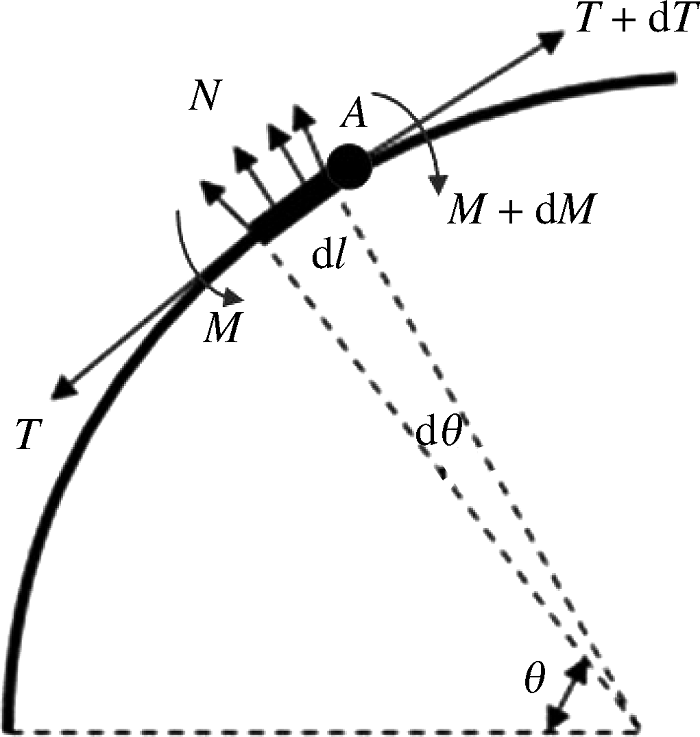
静态条件下,管道在半径为R的下水桥上受到的法向接触荷载N(即挤压力),可由任意的力系平衡关系获得,如文献[12]中采用的力平衡。本文取图1所示铺设管道上任意弧长为dl的单元,对A点取矩,并建立微元的力矩平衡方程:
T sin
式中:T为所取弧段一端受到的张力;Mw为所取弧段自重w对A点的矩,可依据圆弧的重心公式获得[13],
Mw=w·dl·
cos
通常在管道铺设中,弧段质量w与T相比是一个小量,因此Mw项可忽略,且有
sindθ≈dθ,dl=Rdθ,dM=dM=dEI/R=0.
式中:EI为弯曲刚度。
故式(1)可简化为
T·R·
最终得到估算上弯段接触力的简化计算公式:
N=T/R.(2)
在下水桥是半径为R的圆弧时,可用式(2)估计柔性管道与下水桥的接触荷载。但是需要注意的是,在图2所示的升离点A与B附近,管道在自身弯曲刚度的影响下,局部的曲率与径向变形都将发生变化,并且在其影响的区域内受到的接触反力都将增大。这是因为上述区域内的管道不再是曲率半径固定的圆弧,且dM≠0,因而不满足应用式(2)的条件。
图2 上弯段接触变形与升离点示意图
Fig.2 Schematic of contact deformation and lifting points of over-bend
可以推断管道在下水桥上接触力最大的位置将在升离点附近,且接触力的大小将与如下4个参数有关:铺设张力T、下水桥半径R、管道的弯曲刚度、管道与下水桥间的接触刚度。这涉及到几何大变形和接触等非线性问题。为验证上述推论,借助数值手段进行分析。下面将借助OrcaFlex软件,验证动态铺设工况下接触荷载的分布,并对上述参数进行灵敏度分析。
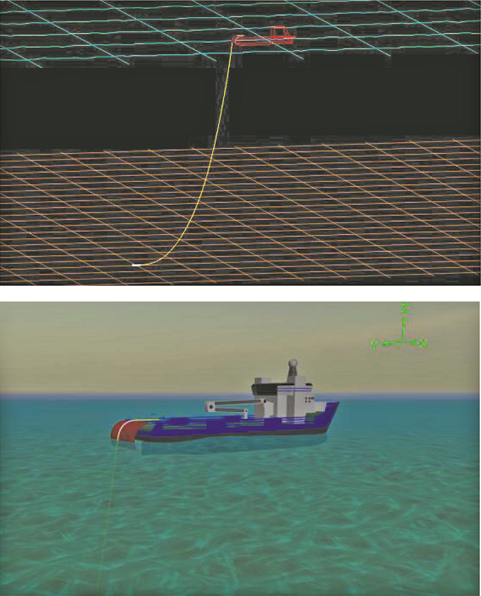
以300 m水深、12英寸(1英寸=2.54 cm)典型柔性管道的铺设为例,对上弯段接触问题进行研究。采用非线性时域分析方法,分析动态海洋环境下铺设管道的动态响应。考虑南海的典型波浪谱(Johnswap谱),并假设允许施工的最大有义波高为Hs=2.0 m,相应的谱峰周期Tp=6.1 s。为简化分析,选择铺管船迎浪的情形(迎浪角为0°)进行建模分析。
在OrcaFlex中建立的模型如图3所示;主要参数如表1所示。其中管道与下水桥的初始接触位置(即上端升离点处)在距管端10 m处。
表1 模型主要参数
Table 1 Main parameters of the model
| 铺管船参数 | 数值 |
|---|---|
| 船长/m | 80 |
| 下水桥半径/m | 6 |
| 管道与下水桥摩擦系数 | 0.3 |
| 管道外径/mm | 450 |
| 管道最大允许挤压力/(kN·m-1) | 120 |
| 管道拉伸刚度/MN | 1 600 |
| 管道弯曲刚度/(kN·m-2) | 600 |
| 铺设脱离角/(°) | 8 |
| 管道与下水桥接触刚度/(kN·m-2) | 10 000 |
2.2.1 铺设张力
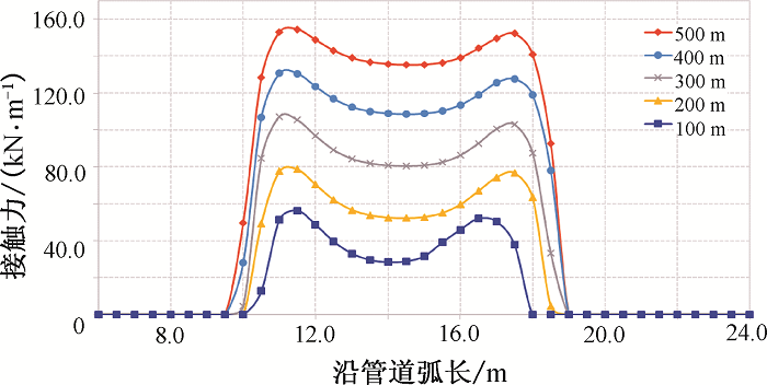
对于给定的柔性管道,不同的铺设张力一般反映为不同的铺设水深,因此,分别考查100,200,300,400,500 m水深的情形。分析结果如表2和图4所示。
表2 铺设张力与接触力
Table 2 Maximun contact forces and pipe laying tensions
| 水深 | 最大张力/kN | 上弯段最大接触力 /(kN·m-1) |
|---|---|---|
| 100 | 184 | 56.3 |
| 200 | 333 | 78.6 |
| 300 | 506 | 107 |
| 400 | 676 | 131 |
| 500 | 839 | 154 |
从上述结果可以看出,铺设水深和铺设张力增加,接触力也随之增加。最大接触力发生在上端升离点处,其值与末端升离点值较为接近,且显著大于接触中间区域,形成图4所示的“驼峰”现象。并且因为“驼峰”的存在,最大张力与最大接触力并不是呈现式(2)的关系。尽管如此,在远离升离点的接触区域,张力与接触力的关系仍近似满足式(2)。
2.2.2 下水桥半径
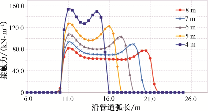
仅改变下水桥的半径,分别设为4,5,6,7,8 m,动态分析的结果如表3和图5所示。
表3 不同下水桥半径下的最大接触力
Table 3 Maximum contact forces under different over-bend radii
| 下水桥半径/m | 最大接触力/(kN·m-1) |
|---|---|
| 4 | 152 |
| 5 | 127 |
| 6 | 107 |
| 7 | 92.9 |
| 8 | 81.8 |
结果显示,下水桥半径越小,柔性管道与下水桥的接触力越大。同样,在下水桥半径足够大时,远离两个升离点的接触力仍然近似满足式(2)。
2.2.3 弯曲刚度
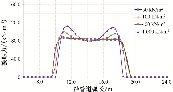
考虑典型的海洋柔性管道的弯曲刚度,分别考虑弯曲刚度50, 100, 400, 1 000 kN/m2时的接触力,分析结果如表4和图6所示。
表4 不同弯曲刚度下的最大接触力
Table 4 Maximum contact forces under different bending stiffnesses
| 弯曲刚度/(kN·m-2) | 最大接触力/(kN·m-1) |
|---|---|
| 50 | 86.2 |
| 100 | 89.1 |
| 400 | 100 |
| 1 000 | 112 |
从图6可以看出,升离点附近接触力的“驼峰”现象主要是由柔性管道的弯曲刚度引起的,在弯曲刚度足够小时(如该例中小于100 kN/m2),升离点附近的接触力不会有显著增加。结合前面的理论研究可以推断,dM≠0是造成“驼峰”现象的主要原因,在弯曲刚度趋近于零时,无论接触刚度多大,都不会产生“驼峰”,此时可以采用式(2)进行估计。但是随着弯曲刚度的增大,升离点附近的接触力将越来越显著。这意味着一般情况下,管道口径越大,“驼峰”现象越显著。
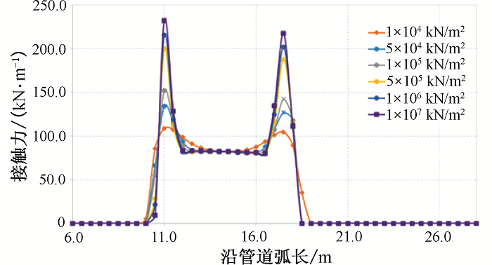
2.2.4 接触刚度
在OrcaFlex中,接触力是通过接触物体的刚度和接触面积计算的,而柔性管道与下水桥之间的接触,不满足经典赫兹理论的基本假设[14],因此其接触刚度与接触面积很难用理论预测。但是在计算铺设中的上弯段时,该值的准确与否尤为重要。假定接触面积为一定值,改变物体的接触刚度分析,结果如表5和图7所示。
表5 不同接触刚度下的最大接触力
Table 5 Maximum contact forces under different contact stiffnesses
| 接触刚度/(kN·m-2) | 最大接触力/(kN·m-1) |
|---|---|
| 1×10⁴ | 108.9 |
| 5×10⁴ | 134.1 |
| 1×10⁵ | 152.3 |
| 5×10⁵ | 200.1 |
| 1×10⁶ | 215.6 |
| 1×10⁷ | 232.3 |
本文所选取12英寸柔性管道在下水桥上所允许的最大接触力约为 120 kN/m。从以上结果来看,接触刚度越大,接触力也将越大,并且可能超出管道所允许的值。因此,接触刚度的设置不仅可能为动态计算带来收敛难题[11],还将影响工程中对管道铺设的设计与决策。
柔性管道采用水平式铺设时,对上弯段的挤压荷载需要进行准确估计。本文对柔性管道水平式铺设的上弯段接触荷载进行了理论研究与数值动态分析,考察了不同参数对接触力的影响,得到了以下主要结论:
(1) 水平式铺设上弯段接触力的简化公式[式(2)]适用于远离升离点的接触区域或管道弯曲刚度很小的情形。但是其揭示的趋势在数值分析中得到了验证,即铺设张力越大,接触荷载越大;下水桥半径越大,接触力越小。
(2) 柔性管道会在升离点附近产生“驼峰现象”,即升离点附近的接触力大于其他区域,该值的大小不仅符合式(2)揭示的趋势,而且随着弯曲刚度和接触刚度的增大而增大。
(3) 弯曲刚度和接触刚度对上弯段接触荷载的影响是耦合的。本文仅基于12英寸典型柔性管道的性能,分别对各参数进行了研究,以供设计参考。但是二者耦合作用的机理及影响程度需要深入探讨。此外,由于柔性管道复杂的截面特性,导致接触变形与接触刚度的预测也是非常困难的。因此,还需要借助理论和试验手段,对柔性管道水平式铺设的上弯段问题展开进一步研究。
The authors have declared that no competing interests exist.
| [1] |
海洋柔性管道骨架层压溃的有限元分析 [J].DOI:10.3969/j.issn.1006-7043.201302003 URL [本文引用: 1] 摘要
针对海洋柔性管道互锁型骨架层 由于外部静水压力可能引起压溃失效问题,文中基于有限元分析方法,采用实体单元,建立骨架层结构三维有限元模型,研究静水外压作用下骨架层的压溃行为.分 析结果显示,当不考虑几何缺陷及材料非线性时,计算得到的压溃特征值与解析方法得到结果吻合良好;当模型考虑初始椭圆度缺陷时,压力位移曲线经过一段线性 变化过程后快速趋近于临界压溃值,且随着初始椭圆度的增大,临界压溃值逐渐减小;当模型进一步引入材料非线性时,骨架层的抗压溃能力显著下降,临界压溃值 比理想状态下减小近一半.数值模型与结果为柔性管道抗压溃分析设计提供了有效的技术手段.
|
| [2] |
海洋柔性管的抗拉性能及加强设计 [C]. |
| [3] |
Analytical study of the mechanical strength of flexible pipes [J]. |
| [4] |
Validation of a computer model for flexible pipe crushing resistance calculations [C]. |
| [5] |
Crushing of flexible pipes under traction: a theoretical-experimental assessment [C].
|
| [6] |
Local mechanical behavior of flexible pipes subjected to installation loads [C]. |
| [7] |
API RP 17B. Recommended practice for flexible pipe [S]. |
| [8] |
API RP 2RD. Design of risers for floating production systems (FPSs) and tension leg platforms (TLPs) [S]. |
| [9] |
Review of flexible riser modelling and analysis techniques [J].DOI:10.1016/0141-0296(95)00027-5 URL [本文引用: 1] 摘要
The past decade has seen significant developments in the use of flexible risers for floating production duties throughout the world. The technological developments in the construction of these pipes have, in parallel, been followed by advances in the analysis of their hydrodynamic and mechanical behaviour. At present, the hydrodynamic analysis is well established with several commercial analysis packages at the disposal of designers. The analysis of flexible pipe mechanical behaviour has produced new analytical and numerical models for the prediction of pipe internal wear and fatigue behaviour. These models are currently being exploited in the optimization of pipe construction and design. New issues of reliability and risk assessment are also entering the scene and are beginning to influence the development of design codes for flexible risers. This paper presents an historical overview of the development of hydrodynamic analysis techniques for flexible risers. It highlights key issues addressed during these developments including the effects of internal and external hydrostatic pressures and of internal flow. The paper also presents an overview of the current status of analysis techniques for flexible riser design and engineering and identifies those uncertainties that remain.
|
| [10] |
Global analysis of a flexible riser [J].DOI:10.1007/s11804-011-1094-x URL [本文引用: 1] 摘要
The mechanical performance of a flexible riser is more outstanding than other risers in violent environmental conditions.Based on the lumped mass method,a steep wave flexible riser configuration attached to a Floating Production Storage and Offloading(FPSO)has been applied to a global analysis in order to acquire the static and dynamic behavior of the flexible riser.The riser was divided into a series of straight massless line segments with a node at each end.Only the axial and torsional properties of the line were modeled,while the mass,weight,and buoyancy were all lumped to the nodes.Four different buoyancy module lengths have been made to demonstrate the importance of mode selection,so as to confirm the optimum buoyancy module length.The results in the sensitivity study show that the flexible riser is not very sensitive to the ocean current,and the buoyancy module can reduce the Von Mises stress and improve the mechanical performance of the flexible riser.Shorter buoyancy module length can reduce the riser effective tension in a specific range of the buoyancy module length when other parameters are constant,but it can also increase the maximum curvature of the riser.As a result,all kinds of the riser performances should be taken into account in order to select the most appropriate buoyancy module length.
|
| [11] |
Orcina Ltd. OrcaFlex User Manual, v9.5a [EB/OL]. . |
| [12] |
海底柔性管道铺设设计与分析技术研究 [D].
|
| [13] |
|
| [14] |
|

/
| 〈 |
|
〉 |
