Figure 3 shows the electrochemical performances of the SiNDs/C, VG@SiNDs/C, and MPCF@VG@SiNDs/C electrodes in coin-type half cells. Note that these electrodes were tested at the same areal capacity of about 3.8 mAh cm
−2. Different from the SiNDs/C and VG@SiNDs/C electrodes, the MPCF@VG@SiNDs/C electrode can be fabricated under industrial electrode conditions (areal capacity loading ≥ 3.3 mAh cm
−2, binder ≤ 3 wt%, conductive agents ≤ 1 wt%) [
34]. Specific explanations are given in the experimental section in Supporting Information. At a current density of 0.1 A g
−1, the first charging capacity of SiNDs/C, VG@SiNDs/C, and MPCF@VG@SiNDs/C is 2134.6, 1794.6, and 1512.2 mAh g
−1, respectively (
Fig. 3a). The capacity mainly depends on the amount of Si in the sample (calculated in
Fig. 2f). The voltage profile of SiNDs/C is quite different from that of pure Si electrode [
9]. It may be attributed to the mixed products like Si, Si-O, Si-O-C, and the nanoscale carbon matrix in SiNDs/C. MPCF@VG@SiNDs/C with the lowest specific surface area delivers the largest initial Coulombic efficiency (CE) of 86.6%. Although the first charging capacity of MPCF@VG@SiNDs/C is slightly lower than SiNDs/C and VG@SiNDs/C, it exhibits the highest capacity retention of 102.0% after 100 cycles, in comparison with 95.7% for VG@SiNDs/C and 89.4% for SiNDs/C (
Fig. 3b, Table S3). The lowest capacity retention of SiNDs/C is largely owing to the lack of space for Si expansion and its high Si contents on the particle surface (repeatedly consuming the electrolyte). This can also be confirmed by the significantly increased electrode thickness (57.0%) and the numerous cracks on the electrode surface after cycling (Fig. S18). Growing flexible VG on the SiNDs/C surface not only covers the exposed Si on the particle surface, but also buffers the volume change of the SiNDs/C, thus improving the cycle stability of VG@SiNDs/C. By comparison with SiNDs/C, VG@SiNDs/C also shows a reduced thickness change of 28.4% with little cracks on the surface after cycling (Fig. S19), demonstrating enhanced structural stability. After welding VG@SiNDs/C to the walls of MPCF, MPCF@VG@SiNDs/C with enough expansion space and interconnected carbon structure brings the best cycling stability over other samples. In addition, the MPCF@VG@SiNDs/C electrode remains intact with an ultralow thickness expansion of 1.1% (Fig. S20), suggesting its unique low-strain properties to ensure excellent cycling stability.
Figure 3c shows the rate performance of samples assessed by ramping current densities from 0.1 to 20 A g
−1. At 2 A g
−1, the capacity of MPCF@VG@SiNDs/C maintains at 1288.6 mAh g
−1, corresponding to 85.2% of the capacity at 0.1 A g
−1 (1512.8 mAh g
−1). Even after cycling at 10 and 20 A g
−1, MPCF@VG@SiNDs/C still delivers advanced invertible capacities of 1045.4 and 910.3 mAh g
−1, respectively. Moreover, absolute recovery of the capacity is achieved when the current density returns to 0.1 A g
−1. By comparison, although delivering high capacity at lower current densities (< 2 A g
−1), the VG@SiNDs/C and SiNDs/C exhibit far inferior rate capacity than MPCF@VG@SiNDs/C at high current densities (> 5 A g
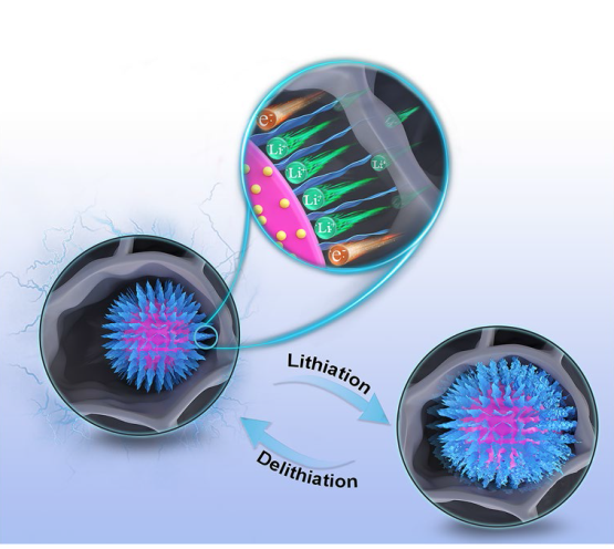
−1). Such superior rate capacity of MPCF@VG@SiNDs/C is mainly ascribed to that the few-layered VG: (1) provides directed and continuous channels to accelerate Li
+ transport and (2) ensures highly efficient charge transfer at the interfaces between internal SiNDs and external MPCF (inset of
Fig. 3c). In addition, all these samples remain stable during the rate testing process, as confirmed by the similar charge/discharge profiles at each current density (
Fig. 3d-f). To further reveal the reason for the excellent rate capability of MPCF@VG@SiNDs/C, the EIS study was carried out (
Fig. 3g-i) and was fitted by the equivalent circuit (Fig. S21). For the Nyquist plots, the diameter of the semicircle reflects the charge transfer resistance (
Rct), the slope of the sloping line corresponds to the Warburg impedance (W) of Li
+ diffusion, and the value of the intersection with the
x-axis is related to the electrolyte resistance (
Rs) [
35]. The corresponding values are listed in Table S4. MPCF@VG@SiNDs/C delivers the lowest
Rct,
Rs, and SEI layer resistance (
Rf), as well as the largest straight-line slope compared to VG@SiNDs/C and SiNDs/C, indicating superior charge transport capability. It is important to note that the nano-sized VG@SiNDs/C, as opposed to micro-sized MPCF@VG@SiNDs/C, results in a reduced tap density and electrode compaction density (
Fig. 2i), thereby causing a notably increased electrode thickness under the same areal capacity conditions (Figs. S19c and S20c). The increased electrode thickness undoubtedly extends the charge transport distance. Additionally, the contact resistance between VG@SiNDs/C particles is heightened due to the nano-sized dimensions of VG@SiNDs/C when compared to micro-sized MPCF@VG@SiNDs/C. Therefore, despite VG@SiNDs/C's larger specific surface area, which results in better wetting between VG@SiNDs/C and electrolyte than that between MPCF@VG@SiNDs/C and electrolyte, the VG@SiNDs/C electrode continues to exhibit a larger interfacial
Rct. These results strongly support the best rate capability of MPCF@VG@SiNDs/C in
Fig. 3c. In addition, the
Rct of these samples continues to decrease during cycling. This is mainly caused by the activation and stabilization of the electrode [
36].


